


Three Phase Three Wire Type Mitsubishi Driver QH42P With Intelligent
- Ref Price:
-

- Loading Port:
- China main port
- Payment Terms:
- TT OR LC
- Min Order Qty:
- 1 kg
- Supply Capability:
- 2300 kg/month
OKorder Service Pledge
OKorder Financial Service
You Might Also Like


Specification
Three phase three wire type.
Number of measuring circuits: 1 circuit.
Measurement items: power consumption (consumption and regeneration), current,
voltage, power, power factor, etc. it is a product group of elevtric energy
measurement modules that can simply measure a variety of energy information.
With only one module, you can measure various detailed information related to
power (consumption and regeneration), reactive power, current, voltage, power,
power factor and frequency. Mitsubishi 1 / O module user manual.
The minimum and maximum values can be continuously monitored without ladder
program, and two types of upper / lower limit alarm qh42f can be executed. The
power used by the output device can be measured only during the on state.
Therefore, the power during the operation of the equipment and the power in the
beat unit can be obtained. Using 3-phase 3-wire products in one slot can
measure up to 4 circuits, and using 3-phase 4-wire products can measure up to 3
circuits
Therefore, through multi circuit products, electric energy measurement can be
implemented in a small space. Mitsubishi / O module user manual. For example,
one module can be used to measure other loads from the control panel trunk
line.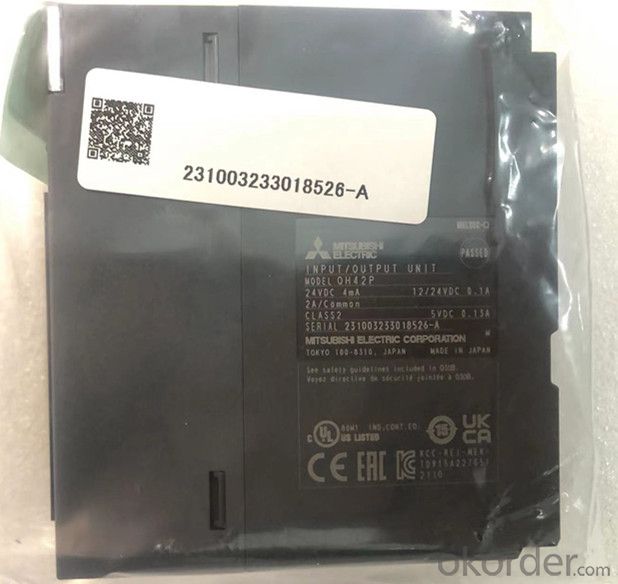
In addition, GX works2 (version 1.90u and higher) can be used to easily set
parameters and bidirectional controllable brick output; 32 o'clock. Rated
current and voltage: AC100 ~ 240V_ 0.6a/1 point, 2.4a/1 public end, 8:1 public
end Mitsubishi / O module user manual. Response time: 1ms + 0.5 cycle.
External wiring connection mode: 38 point terminal block (terminal block is
sold separately). Replacement model: ay23, output: 2 channels,
Input (resolution): 0 ~ 4000: - 4000 ~ 4000:0 ~ 12000-12000 ~ 12000: - 16000 ~
16000 output: DC-10 ~ 10V: dc0 ~ 20maqh42p user manual. Conversion speed: 80us
/ 1 channel. 18 point terminal block.
Transformer isolation between power supply and output. High insulation strength
and withstand voltage.
It can isolate electrical interference, such as current and noise. Standard
analog input module. Isolated analog input module. No external isolation
amplifier is required.
When the inter channel isolated analog quantity module is not used.
Qh42p user manual when using inter channel isolated analog module. Expand the
possibility of control with intelligent functions.
Provide various analog modules, which is an ideal choice for process control
applications. It can also meet the needs of high-speed and high-precision
control.
It is most suitable for analog modules in the field of high-speed conversion
control,
Qh42p user manual for a variety of analog-to-digital and digital to analog
conversion module products can be provided
These modules have various functions and achieve maximum flexibility when
connecting devices.
It can meet the needs of high-speed conversion such as frequency converter
control. Various modules with excellent performance
Meet various control requirements from analog quantity to positioning.
Q series module products include a wide variety of / 0, analog and positioning
function modules.
It can fully meet the input and output of switches and sensors, the control of
temperature, weight, flow, motor and driver, and the positioning of high-
precision control in the future! Control requirements in various fields
It can also be combined with CPU module to realize appropriate control. Input
voltage range: AC100-240V. Output voltage: DC5V Output power supply: 2A Ultra
thin power supply. Simplify program debugging
The software component test function with execution conditions can be used to
change the software component value to the user specified value at any step of
the program.
In the past, when debugging a specific circuit program section, it was
necessary to add a program for setting soft components
At present, by using this function, specific loop program segments can perform
actions independently without changing the program. Large, there is no need to
change the program for debugging in the single, the debugging operation is
simple, and the key data is automatically backed up
Automatically save the program and parameter files into the program memory
(flash ROM) without using the backup battery, so as to prevent the program and
parameters from losing the qh42p manual due to forgetting to replace the
battery. In addition, important data such as software component data can be
backed up to standard ROM to avoid planned downtime during long holidays,
These data are lost due to battery depletion. Mitsubishi / / O module user
manual. The next time the power is turned on, the backed up data will be
restored automatically. Through the extension of software components, it is
more convenient to create programs.
The software component can be extended to 60m bits at most
- Q: Hi, can somebody please help me with this inductor problem? I'm stuck on it and need some help i think that I have the general idea, but need some guidance.
- This is a step-value function and will need to be solved piece-wise. For t 0 to 5us: Since I (1/L) Vdt therefore:: I (1 / 2E-3) * 10V * 5us 500 * 10V * 5us 25mA For t 5us to 15us I (1 / 2E-3) * -10V * 10us 500 * -10V * 10us -50mA For t 15us to 20us I (1 / 2E-3) * 10V * 5us 500 * -10V * 5us 25mA The total current from t 0 thru t 20us 25mA -50mA +25mA 0 mA
- Q: An inductor has the form of a coil with 2050 turns and a diameter of 1.4 mm. The inductor is placed in a magnetic field perpendicular to the plane of the coil and increasing at a rate of 0.23 T/s. The current in the inductor is zero at t 0, and then increases to 6.6 mA at t 1.0 s. What is the inductance? (in mH)
- The emf in the inductor is: V n*A*ΔB/Δt Calculate the area of the coil: A π*r^2 π*(.0014/2)^2 1.54*10^-6 m^2 V 2050*(1.54*10^-6)*(.23) 726*10^-6 V Also: V L*dI/dt L V/(dI/dt) 726*10^-6/(6.6*10^-3) 110*10^-3 H 110 mH
- Q: How do I figure out inductor equivalence when you have a series parallel combination inductor circuit
- treat them as they where resistors sum them up when in series .parallel them when in parallel
- Q: A 0.56-m H inductor stores 3.5×10⁻⁵ J when carrying a DC current. What is the magnitude of that current?
- 3.5×10⁻⁵ J (1/2) 0.56 x10^-3 i^2 i 0.356 A
- Q: An LC circuit consists of a capacitor, C 1.72 μF, and an inductor, L 5.32 mH. The capacitor is fully charged using a battery and then connected to the inductor. An oscilloscope is used to measure the frequency of the oscillations in the circuit. Next, the circuit is opened, and a resistor, R, is inserted in series with the inductor and the capacitor. The capacitor is again fully charged using the same battery and then connected to the circuit. The angular frequency of the damped oscillations in the RLC circuit is found to be 19.5% less than the angular frequency of the oscillations in the LC circuit. a) Determine the resistance of the resistor. b) How long after the capacitor is reconnected in the circuit will the amplitude of the damped current through the circuit be 19.0% of the initial amplitude? c) How many complete damped oscillations will have occurred in that time?
- Here is an earlier Answer to the same Question: .
- Q: Cant seem to get my head around this question so any advice would be greatA circuit with an inductor(with both resistance and inductance) Vrl (200+j300)V connected in series to a capacitor c150 micraF across a power supply with a 50Hz supply voltage. The supply current is 25lt;0 degreesCalculatea) impedance of the inductor expressed in complex formb) the values of R and L of the inductorc) the value of the supply voltage, expressed in polar formd) the phase angle of the circuite) the apparent and active powers of the circuitf) draw a scaled argand diagram showing the supply current and all voltages
- Vrl 200 + j 300 Vrl √[200? + j300]? 360.56 Vrms 56.31 degrees R Zr 200 V / 25A 8 Ohm Is 25A 0 degrees Zrl 360.56 Vrms 56.31 degrees / 25 A 0 degrees Zrl 14.42 Ohm 56.31 degrees Zrl 8 Ohm + j12 Ohm f 50Hz C 150 μF Zc -1/2πfC Zc -1/(100π(.00015)) Zc -j21.22 Ohm Zr + Zc Zrc Zr 8 + j00.00 Ohm Zc 0 - j21.22 Ohm Zrc 8 - j21.22 Ohm Zrl - Zrc Zl Zrl 8 + j12.00 Ohm Zrc 8 - j21.22 Ohm Zl 0 + j33.22 Ohm Zl 33.22 Ohm Zl 2 π f L L Zl/ 2 π f 33.22 Ohm /(100 x π) .105743 L 105.743 mH Zt Zr + Zl + Zc Zr 8 + j00.00 Ohm Zc 0 - j21.22 Ohm Zl 0 + j33.22 Ohm Zt 8 + j12.00 Ohm Zt 14.42 56.31 degrees Is 25A 0 degrees Vt (14.42 56.31) x (25A 0) 360.5 Vrms 56.31 degrees Pt 360.5 Vrms 56.31 degrees x 25A 0 degrees 9012.5 56.31 W Is? 25A? 0 degrees 625 A? 0 Pr 8 Ohm x 625A? 5000 W Pc - j21.22 Ohm x 625A? -13262.5 VAR Pl j33.22 Ohm x 625A? 20762.5 VAR Pt 5000 W + 7500 VAR Pt 9013.9 VA 56.31 degrees a) impedance of the inductor expressed in complex form Zl 0 Ohm + 33.22 j Ohm b) the values of R and L of the inductor R Zr 200 V / 25A 8 Ohm L 105.743 mH c) the value of the supply voltage, expressed in polar form Vt (14.42 56.31) x (25A 0) 360.5 Vrms 56.31 degrees d) the phase angle of the circuit φ 56.31 degrees e) the apparent and active powers of the circuit Pr 8 x 625A? 5000 W Pt 5000 W + 7500 VAR Pt 9013.9 VA 56.31 degrees f) draw a scaled argand diagram showing the supply current and all voltages Let me goI won't make itYou go on ahead without me :)
- Q: An RLC circuit has a 400 ohm resistance a 2.5 mH inductor and a capacitor. If the circuit is in resonance at 30kHz and is attached to a 20mVrms power supply, what is the power dissipated by the circuit?
- I'm assuming that the power supply is at the resonant frequency. Therefore, by definition, at resonance the series impedance of the inductor and capacitor equals zero. The power supply therefore sees just a 400 ohm resistor. Therefore the power dissipation is given by V^2/R, which equals 1 microwatt.
- Q: Here is the diagram
- Do your own homework. Use some calculus skills.
- Q: how to calculate SRF of a inductor?
- Inductor Design. (1) Single layer air cored. L N2?r? / 254(0.9+I) L inductance in uH. N number of turns. I coil length in mm. r coil radius in mm. (2) Multi-layer air cored, height equal to inner radius. H 0.34 √L/R. N 19.9 √L/H. L inductance in uH. N number of turns. H coil height in mm. d wire diam. in mm. R coils d.c. resistance in Ohms. (3) Multi-layer with height half the inner radius. H 0.323 √L/R. N 13.2√L/H. d 0.736H/√N. symbols the same as (2). (4) Coils wound on ferrite toroids or similar. N T√L/AL. L inductance of coil. A the inductance of T turns of the particular core. Coils wound on ferrites having an open loop, their design is based on the formula for air coiled coils, as shown in (1). The final inductance is usually found by trial and error but is typically 2 to 3 times the air cored inductance.
- Q: A 33.0-mH inductor has a reactance of 2.20 kΩ. (a) What is the frequency of the ac current that passes through the inductor?(b) What is the capacitance of a capacitor that has the same reactance at this frequency?(c) The frequency is tripled, so that the reactances of the inductor and capacitor are no longer equal. What is the new reactance of the inductor?(d) What is the new reactance of the capacitor?I've been stuck on this physics problem. Please Help!! Thanks so much!!
- 2200 Ohms 2 Pi (f Hz) (0.033 Henry), thus f 10610 Hz 2200 Ohms 1 / (2 Pi (10610 Hz) (C Farad)), thus C 6.818 nF Continue with these two relationships to answer (c) and (d)
Send your message to us
Three Phase Three Wire Type Mitsubishi Driver QH42P With Intelligent
- Ref Price:
-
- Loading Port:
- China main port
- Payment Terms:
- TT OR LC
- Min Order Qty:
- 1 kg
- Supply Capability:
- 2300 kg/month
OKorder Service Pledge
OKorder Financial Service
Similar products
Hot products


Hot Searches
Related keywords

