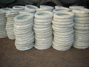
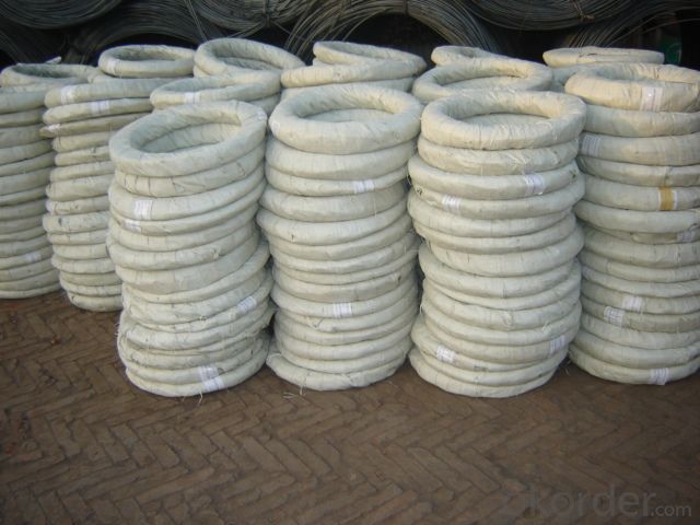
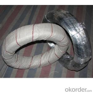
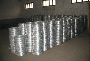
electric galvanized iron wire for binding used construction
- Ref Price:
-

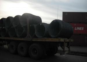
- Loading Port:
- Tianjin
- Payment Terms:
- TT OR LC
- Min Order Qty:
- 5 m.t.
- Supply Capability:
- 500 m.t./month
OKorder Service Pledge
OKorder Financial Service
You Might Also Like


popular electric galvanized iron wire for binding
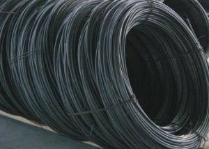
We can supply super quality Electro Galvanized Iron Wire/ Hot Dipped Galvanized Wire processed with low/hign carbon steel wire, through drawing and electro
galvanizing.Our Fivestar produces Galvanized Wire from choiced low/high carbon steel wire, through the strict process of wire drawing-annealing-acid washing-water clearing-drying-galvanizing
coiling, in this way, excellent flexibility and tensile strength could be guaranteed.
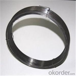
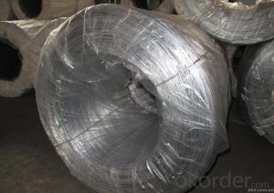
Electric Galvanized Wire
Brand: LONGHONG (High Reputation)
Standard: ASTM ,BS,EN
Certificate: ISO9001
Nominal Dia.: 0.24-5mm
T/S: 300-1200 Mpa
Reel : 5-500kg/coil
Packing: By coil , or by spool according to different dia, one water-resistent tag.
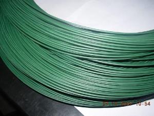
Applications
Detonator lead,artware, redrawing
Specifications
ZINC COATING
Electric Galvanized Wire
Brand: LONGHONG (High Reputation)
Standard: ASTM ,BS,EN
Certificate: ISO9001
Nominal Dia.: 0.24-5mm
T/S: 300-1200 Mpa
Reel : 5-500kg/coil
Packing: By coil , or by spool according to different dia, one water-resistent tag.
Applications
Detonator lead,artware, redrawing
- Q: Wire diagram
- Hello there George, It has become common over the past few years that non-residential boilers are wired with EPO (emergency, power off) switches just outside each door to the boiler room. This is similar to having fire alarm pull boxes by the exits. I do not know of any jurisdiction that requires it for a residence. On occassion I've seen the 24 volt circuit for the thermostat being switched, which is a bit sketchy. Normally the 120 volt circuit for the controller is switched. The switches used are of the pushbutton type.
- Q: I have a 1990 chevy c1500 2wheel drive. I bought it not running. I have found the problem and it the tbi injectors are not hooked up. The 4 wires on the 2 injectors are red and the 4 wires going to the tbi are red,blue,green,white. what wires go were? Thanx for all your help.
- The red and white wires are the power to each injector and are actually hooked to each other in the harness. These 2 wires should be hot when you turn the key on. The green and blue wires are the grounds that lead back to the ecm. The red and blue wires go to the passenger side injector (red is far left as you face the vehicle). The white and green go to drivers side (white on left as you face it)
- Q: i have a purple wire i have no clue what it goes to, i have a dark blue/brown wire i dont know what it goes to and want to make sure the i just cap off the orange wire…Can someone please help me-it is draining my battery
- go to an xpert no1 over here can help u on ds :) enjoy
- Q: So basically my i have a ps3 wired controller but the problem is the wire any jerks or movement at all and it will shut off and i have to repeatedly press the home button to turn it on i am 100% sure its the wire any ideas on how to fix this problem?
- It sounds like the wire is loose. To fix this, you'll have to open up the controller and reattach/secure it. If the wire is exposed and is frayed, you'll probably have to get a new controller. This is very broad because you didn't specify the model of the controller. Some of the wired controllers use the normal Ps3-USB wire, while others do not. So, trying opening it up and securing the wire. If you're lucky and it's a Ps3-USB wire, replace it with a new wire. Otherwise, you'll have to get a new controller if you can't fix it.
- Q: The drawing shows two long, straight wires that are suspended from the ceiling. The mass per unit of length of each wire is 0.050kg/m. Each of the four strings suspending the wires has a length of 1.2m. When the wires carry identical currents in opposite directions, the angel between the strings holding the two wires is 15 degrees. What is the current in each wire?? Im not sure what equations to use for this problem.
- Look at it this way a current I2 causes a magnetic field. if a current I1 is in a magnetic field then a force acts on it. F=I1*B*dl where B=I2*(mu0)/(2*pi*d) So the force between those two wires is given by this equation F=I1*I2*(mu0)*dl/(2*pi*d) mu0=4*pi*10power7 d the distance between them In this case I1=I2 dl which shows the lenght of the wire in the magnetic field equals 1 because you do not care about it's lenght from here on it is rather simple I hope
- Q: do you match positives and negatives or positives and positives when wiring a car stereo
- Radio Constant 12V+ Wire: Light Green/Purple Radio Switched 12V+ Wire: Yellow/Black Radio Ground Wire: Black Radio Illumination Wire: Red/Black Radio Dimmer Wire: N/A Radio Antenna Trigger Wire: N/A Radio Amp Trigger Wire: N/A Front Speakers Size: N/A Front Speakers Location: N/A Left Front Speaker Wire (+): Orange/Light Green Left Front Speaker Wire (-): Light Blue/White Right Front Speaker Wire (+): White/Light Green Right Front Speaker Wire (-): Green/Orange Rear Speakers Size: N/A Rear Speakers Location: N/A Left Rear Speaker Wire (+): Tan/Yellow Left Rear Speaker Wire (-): Gray/Light Blue Right Rear Speaker Wire (+): Orange/Red Right Rear Speaker Wire (-): Brown/Pink You match the wires from your new unit to the wires of the harness.
- Q: To help clean things up and make wiring a little more simpler on my jeep i got a fuse/relay box off an old junk car. i want to wire my off road lights into this relay box but i'm not sure what size wire is in the box it appears to be either 18 or 16 AWG one place said to strip the wire and measure the wire another says measure in the insulation. i'm not sure what to do. but if it is 18 awg would it hurt to go to a bigger size after the fuse box to my lights or should i rewire the whole box?
- you have a relay wiring kit precise? the possibility of the relay ought to be saved contained interior the engine compartment. after all the possibility of the substitute ought to be proper as follows: discover you fuse block placed contained interior the cab. under sprint left section perhaps (I truthfully have a 'ninety 8 F150, no longer useful of differences) next stumble on an empty slot that isn't in use (no fuse in place). you additionally could make the relationship with a lady flat a million/4 connector to male connector placed on the shrink back of the fuse block. i ought to top be incorrect on the form of connector, yet you will see the way it rather is suitable as quickly as you stumble on it. you may discover the headlight circuit in case you choose them to close off with the headlights. shop in strategies you choose for to coach a relay so it won't overload the headlight circuit when you consider which you're putting on some heafty lighting fixtures furnishings on it. Sorry i'm in a hurry as we talk yet choose this facilitates. i visit make particular shrink back later to substantiate if to any extent further useful perfect ideas are obtainable in, and upload extra useful if needed. good fulfillment guy.
- Q: Ok, bought this mower at an estate auction for next to nothing. It looks like its never been used. Previous owner ripped out all the wires to the ignition switch so it wouldn't sell I guess. It's the craftsman lt 1500. Model number 247.288812. It has the 17.5hp bs motor in it. Does anyone know the correct way the wires go to the switch? There are 3 red wires so its a bit unlike what im used to. Thanks in advance!
- Being okorder or any Sear's store.
- Q: I am wiring a sony xplod amp up in my car and need to know what the skinny blue wire goes to. Any help would be appreciated.
- Run a fused (1 amp, 14 AWG) wire from a fuse in the fuse panel that only has power when the car is ON to one side of a switch. From the other side of the switch run the same sized wire to the REM (remote) connection on the amp. This allows for full control and you never have to worry about forgetting to turn off the amp. The switch is so you can turn off the amp at will so as not to give grandma a heart attack in the car. You can find fuse taps and in-line fuse holders at any autoparts store.
- Q: Say you have a 5 cm current wire carrying 10 A going from left to right. Directly 1 c.m below the left end of this wire is a long wire that is perpendicular to the first wire and goes out of the page. What is the net force on the 5 cm wire?I've tried using F=ILB with the I of the first wire and the B of the second wire.
- I didn't read the question so I was carefully working out the force. The wire is perpendicular to the first wire, so using the right hand rule you discover that the field it creates is PARALLEL to the first wire at this left end. The magnetic force is caused by the component which is PERPENDICULAR to the wire which is in fact zero. So there is no magnetic force at this point. As you move along the wire you get a diminishing amount of magnetism caused by the wire which is going out of the page but that field has a component which is DOWN the page. Therefore that part of the wire experiences a force which is into the page. ( take your right hand, put the thumb along the wire pointing to the right, the fingers point down the page, the palm points into the page which is then the direction of the force) I would be surprised if you were required to work out the magnitude of the force in this context. You can't use F= ILB because both the magnitude and the direction of the field varies at different points along the wire. If the perpendicular wire had been directly below the middle of the other wire there would have been no net force. If you were of a level where working out the force was appropriate you would need to set up the formula for B at various points along the wire, taking the vertical component only and integrate this over the range from 0 to 5 cm. Not a trivial mathematical task.
Send your message to us
electric galvanized iron wire for binding used construction
- Ref Price:
-
- Loading Port:
- Tianjin
- Payment Terms:
- TT OR LC
- Min Order Qty:
- 5 m.t.
- Supply Capability:
- 500 m.t./month
OKorder Service Pledge
OKorder Financial Service
Similar products


Hot products

Hot Searches

