


Concrete Delivery Pipe for Cifa Concrete Pump
- Ref Price:
-

- Loading Port:
- Tianjin
- Payment Terms:
- TT OR LC
- Min Order Qty:
- 20 pc
- Supply Capability:
- 2000 pc/month
OKorder Service Pledge
OKorder Financial Service
You Might Also Like

Concrete Delivery Pipe for Cifa Concrete Pump
1. Structure of Concrete Delivery Pipe for Cifa Concrete Pump:
Include four types
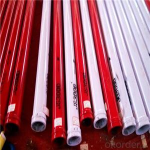
St52 Weld Pipe: Main use for Trailer-mounted pump, thickness has 4.0mm, 4.5mm, 5mm. Compare with for Truck-mounted pump. Weld pipe has cheaper price, so it is popular in Saudi, Pakistan, India, etc. Unit Price is about 30USD-33USD.
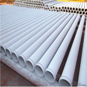
St52 Seamless Pipe: Now More People like use this kind for Truck Pump and Trailer Pump because of the quality is better and it is seamless kind, so this kind pipe is most popular in Middle East Price About 34USD-37USD.
Wear Resistant Pipe: Use for Truck Pump, Wear Resistant Layer is 2.5mm.Through heat treatment way make this pipe more strong (HRC60-62), Using Life: 25,000m³-35,000m³ Price about 65USD-68USD.
Two Wall Pipe: This pipe thickness (2mm+2.5mm), Using Life about 50,000m³-60,000m³
2. Main Features of Concrete Delivery Pipe for Cifa Concrete Pump:
• High Wear-resistant, long service life, lower cost
• In case of quality problem the company provide free replacement.
• Provide technical support for free.
• Provide consumers with regular visits
• Ensure the supply of ancillary parts
• Our company passed the ISO9000 certification, the product through 3C certification in full compliance with national standards
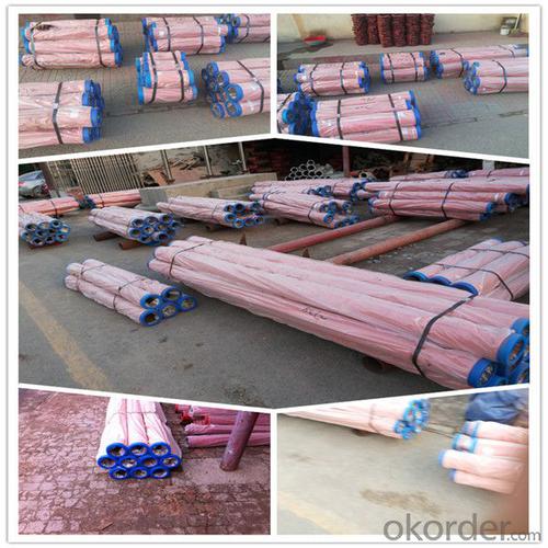
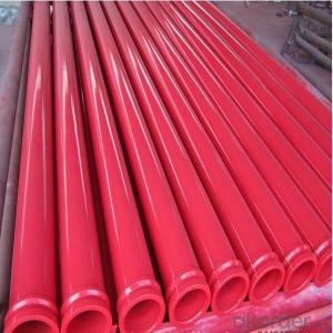
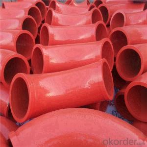
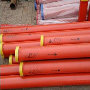
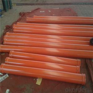
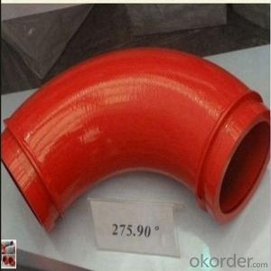
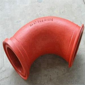
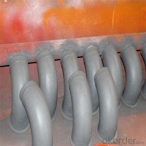
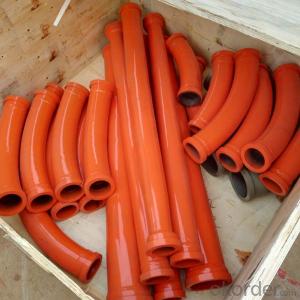
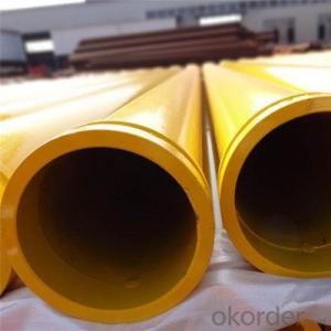
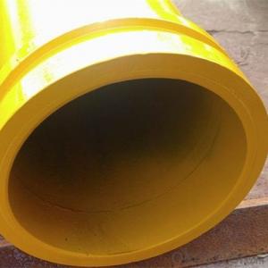
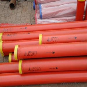
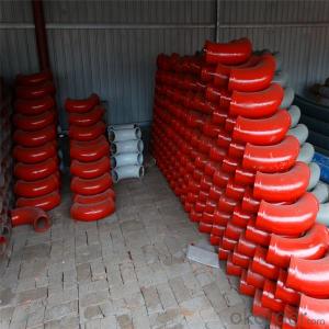
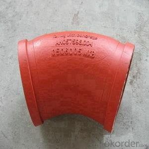
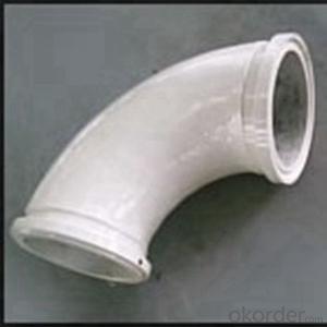
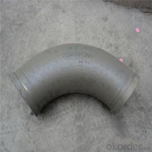
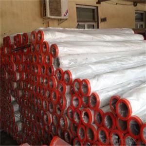
3. Concrete Delivery Pipe for Cifa Concrete Pump Images:


4. Concrete Delivery Pipe for Cifa Concrete Pump Specification:

Name | Data |
Material | 45MN2/20#/16MN/Q345 |
Thickness | According to customer requirements |
Color | red, white , etc. |
Using life | 20.000m³-80.000m³ |
Weight | 43kg,48kg,69kg |
Length | 1-6m, according to customer requirements |
Model | DN125,DN150 |
Flange | SK/ ZX /FM flange |
Painting | Electrostatic Spraying Epoxy Paint |
Welding | Smooth welding between straight pipes and flanges |
Process | High temperature quenching |
HRC | 65 |
Production Process

5. FAQ:
We have organized several common questions for our clients, may help you sincerely:
①Is your products exported a lot?
We have exported to many, many countries. Every year we ship more than 30 containers of these spare parts. Our main market is in Middle-east, Asia & Africa.
②How to guarantee the quality of the products?
We have established the international advanced quality management system,every link from raw material to final product we have strict quality test;We resolutely put an end to unqualified products flowing into the market. At the same time, we will provide necessary follow-up service assurance.
③How long can we receive the product after purchase?
In the purchase of product within three working days, we will arrange the factory delivery as soon as possible. The specific time of receiving is related to the state and position of customers. Commonly 15 working days can be served.
- Q: 3D MAX must set motion for each object. Is there a 3D mechanical design software that can simulate the mechanical movement of the parts?As long as the specified object is motor, coupling, chain, gear, into the simulation, the three-dimensional map of the motor shaft will rotate, and drives the coupling, keys, gear for the corresponding movement, rather like 3D Max that is the true state of motion to each object design movement performance of this machine combination?
- SOLIDWORKSBut it is also necessary to develop the law of motion relative to 3DMAX, but your modeling is a problem,Can you NURBS? SOLIDWORKS does not support polygon modelingIf I import the file, there's only line segments. I haven't found a better wayIt's better to continue using 3DMAX
- Q: In the design of large machinery, it is to design the parts first, the assembly drawings as well
- The design stage to do assembly structure. According to the structure design of parts and related calculation. The choice of materials and structures suitable. The original painting is the first climbing board assembly, and then split the parts of the map.
- Q: What exactly is mechanical design?
- Mechanical design (machine, design),According to the requirement of the mechanical structure, working principle, motion, force and energy transfer, the various parts of the material and shape size and lubrication methods for design, analysis and calculation and put it into specific description as a basis for the manufacturing process.
- Q: Who knows what the design criteria for machine parts are, and how they are designed?
- 5. life standards, in order to ensure that the machine in a certain life span of normal work, in the design of mechanical parts, it is necessary to request the life of mechanical parts. It should be explained that parts can be replaced during the life of the machine, that is, the life of some mechanical parts is shorter than the life of the machine. The life of mechanical parts is mainly affected by fatigue, wear and corrosion of materials. In order to avoid failure caused by parts fatigue, such as fatigue fracture, fatigue strength should be calculated according to the fatigue limit corresponding to the life of mechanical parts. That is to say, according to the requirements of life and the specific speed of parts, according to formula (3-6), the fatigue limit is calculated when the stress cycle number is N. Then the strength condition is calculated and the fatigue strength is calculated. When the fatigue strength is satisfied, the stress cycle times of the mechanical parts can be guaranteed before the damage. Wear is usually unavoidable. Under certain conditions, corrosion is inevitable, such as structural members of bridges, corrosion of buried steel pipelines, etc.. In the design, mainly to ensure the mechanical parts in life, not excessive wear and corrosion. The mechanism of wear is still fully mastered, and there are many factors affecting wear. Generally, the wear resistance of friction pairs is improved according to the tribological design principle. The main measures are as follows: reasonable selection of friction pairs, reasonable choice of lubricant and additives, and control of the working conditions of friction pairs, such as pressure, sliding speed and temperature rise. So far, there is no practical and effective method for calculating corrosion life
- Q: How to design the common mechanical parts with CATIA, and how to solve the problem when the units are inconsistent?
- When you build parameters, type select length, and enter units with values, such as "100mm"
- Q: I am an ordinary graduate, two jobs to me, one is non-standard automatic design work, but the first half of the assembly in the workshop, and then to design. There is also a mechanical component CAD draftsman. After that, you can do part design. May I ask which job will have a future for you?
- Of course, the former is good, the future is infinite, there is no comparison. But you have to design parts for non-standard automation!
- Q: I am a bachelor degree in industrial design and have been sitting here for two months now, 20The feeling is still not understand, not figure painting, other colleagues are busy, I could not ask, do not know how to do, give me a leading figure today, let me figure it out on my own, I draw more and more have no confidence, I do not know because many mechanical components, do not know how to do.. Tired ~ ~ mechanical aspects of the great God, I pointed to the Ming road! Thanks
- A mechanical design is learning by doing, the school learned to pick it up, in addition to learn how to use the design manual, design experience for reference to others
- Q: What are the main principles of mechanical principles and mechanical parts design?
- 4. weight requirements, often in the hands of the parts required lightweight, in the case of mechanical strength to meet the choice of small proportion of materials;5. service life requirements are temporary or long-term use, intends to use a year or 10 years?6., the influence of environmental temperature, environmental temperature changes will affect the expansion of parts;
- Q: their own materials, hope that the older generation can be under the guidance of the younger brother, brother, thank you very much
- 4. secondly, need to know these things into the product planning (or product itself), making the product form, content and behavior, can become useful, desirable, and feasible in economy and technology.5. usually the design requires originality and mechanical design is more improved and the use of existing conclusions. This requires the mechanical designer must understand the machining process.6., the processing technology is a very practical technology, can only operate by their own hands, it is possible to have experience and understanding of the technology. There is no shortcut. It is impossible to get inspiration through books.7., this is my experience for more than 40 years.
- Q: Mechanical design, hardness of the workpiece, how to determine, for example, in the drawings, technical requirements of the hardness value how to get?
- 1. the hardness of the workpiece should be determined to determine the hardness of the workpiece for the design according to the working conditions of the workpiece, such as linear bearings for the hard axis, because the shaft and ball contact stress, the equivalent of the bearing outer ring, so the hardness in 60-64HRC, which requires the use of accumulated experience, can also query the relevant information to obtain.2., because of the hardness requirements, so the need for reasonable material selection and heat treatment methods; or linear bearings used for hard shaft, it is necessary to choose the appropriate material Cr15, and the surface high-frequency quenching. Material can be used in the design manual to select materials, and heat treatment processes are required to refer to the Handbook of heat treatment processes.3., as designers, there is no need to be proficient in materials, knowledge, and heat treatment processes, but it should be understood that no mistakes should be made. For example, the choice of 2Cr13 as linear bearings with the hard shaft, that hardening is not to improve the hardness. Or choose the right material, but there is no corresponding heat treatment, the surface hardness is not guaranteed.
Send your message to us
Concrete Delivery Pipe for Cifa Concrete Pump
- Ref Price:
-
- Loading Port:
- Tianjin
- Payment Terms:
- TT OR LC
- Min Order Qty:
- 20 pc
- Supply Capability:
- 2000 pc/month
OKorder Service Pledge
OKorder Financial Service
Similar products
Hot products
Hot Searches
Related keywords

