


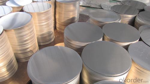
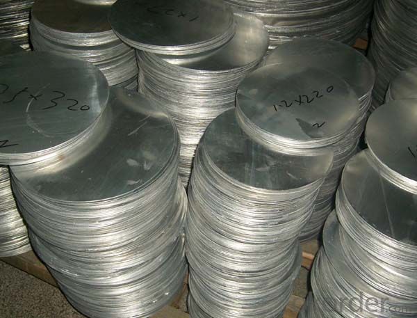
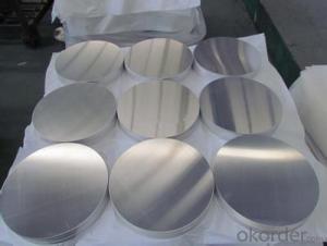
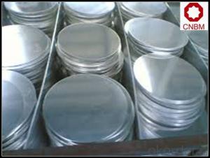
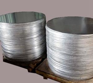
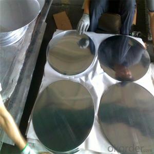
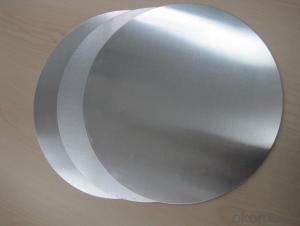
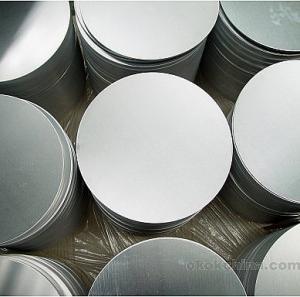
Aluminium Circle/Cookware Aluminium Circle/Aluminium
- Ref Price:
-

- Loading Port:
- Tianjin
- Payment Terms:
- TT OR LC
- Min Order Qty:
- 5 m.t
- Supply Capability:
- 50000 m.t/month
OKorder Service Pledge
OKorder Financial Service
You Might Also Like
Specification
Aluminium Circle/Cookware Aluminium Circle/Aluminium


Parameters
High Quality Aluminium Circle/Cookware Aluminium Circle / Aluminium | |
Brand | CNBM |
Alloy number | 1050,1060,1070,1100,1235, 3003,3004,3102, 5005,5052,5754,5083 6060 8011 |
Temper | O H18 H22 H24 H26 H32 H112 |
Diameter | 10mm-3000mm |
Thickness | 0.02-50mm |
Quality control | ISO9001 SGS QC Qualified tensile strength and elongation |
Application | Mainly used in Construction , decoration, packaging, printing, cover material, piping, electronic elements, referigeration, air conditioner, automobile, etc. |
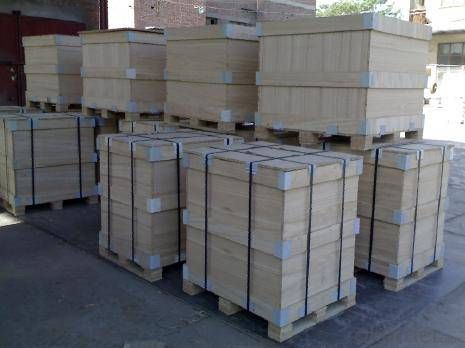
Packing | Seaworthy wooden package with paper interleave, film before wooden package. |
Payment | 100% irrevocable L/C at sight or 30% T/T in advance as deposit and 70% in balance |
Delivery time | 30days after receipt of advance deposit. |
| Mechanical Properties | |||
| TEMPER | THICKNESS(mm) | TENSILE STRENGTH | ELONGATION% |
| HO | 0.55-5.50 | 60-100 | ≥ 20 |
| H12 | 0.55-5.50 | 70-120 | ≥ 4 |
| H14 | 0.55-5.50 | 85-120 | ≥ 2 |
Alloy
Alloy | Si | Fe | Cu | Mn | Mg | Cr | Ni | Zn | Ti | Al |
1060 | 0.25 | 0.35 | 0.05 | 0.03 | 0.03 | --- | --- | 0.05 | 0.03 | 99.6 |
1050 | 0.25 | 0.4 | 0.05 | 0.05 | 0.05 | --- | --- | 0.05 | 0.03 | 99.5 |
1100 | 0.95 | 0.05-0.2 | 0.05 | --- | --- | --- | 0.1 | --- | 99.0 | |
1200 | 1.0 | 0.05 | 0.05 | --- | --- | --- | 0.1 | 0.05 | 99.0 | |
FAQ
Q: Can you provide free samples?
A: Yes, free samples will be sent to you on freight at destination.
Q: Can I get your latest catalogue?
A: Yes, it will b.e sent to you in no time.
Q: What is the MOQ?
A: 5 tons
Q: What are your payment terms?
A: We accept L/C, D/A, D/P, T/T, West Union,etc
- Q: 3D MAX must set motion for each object. Is there a 3D mechanical design software that can simulate the mechanical movement of the parts?As long as the specified object is motor, coupling, chain, gear, into the simulation, the three-dimensional map of the motor shaft will rotate, and drives the coupling, keys, gear for the corresponding movement, rather like 3D Max that is the true state of motion to each object design movement performance of this machine combination?
- Commonly used simulation parts mechanical movement software, ADAMS and SolidWorks Motion module.ADAMS is a professional CAE software, the automatic dynamic analysis of mechanical system (Automatic Dynamic Analysis of Mechanical Systems), the software is the U.S. Mechanical Dynamics Inc (Mechanical Dynamics Inc.) (now part of MSC) the development of virtual prototype analysis software. ADAMS software uses an interactive graphical environment, and part library, library, library capacity constraints, the mechanical system to create fully parametric geometric model, Lagrange equation method of multi rigid body dynamics in the solver using system equations, statics kinematics and dynamics analysis, the virtual machine system, output displacement, speed, acceleration and reaction force. The simulation of ADAMS software can be used to predict the mechanical performance, range of motion, collision detection, peak load, and input load of finite elements.The Motion module of SolidWorks constructs the coordination relation through the constraint form among parts, and completes the simulation of motion between parts.
- Q: What are the key factors in designing mechanical parts?
- 1- reliability. For example, the design of a transmission shaft, to consider whether the uniform load or impact load, axial load or radial load or both, or combined force. In general, even small loads can be fitted with clearance or transition fit, and tolerances can be enlarged so that processing costs are low. For high speed or large load or impact loads, interference fit should be used, such as flywheel shaft of diesel engine.
- Q: Where are the machine parts designed to be finished?
- To the mechanical processing plant ah, there are many machinery processing plants are based on the processing of parts to others to survive, and our products are parts of those machinery factory processing
- Q: I am an ordinary graduate, two jobs to me, one is non-standard automatic design work, but the first half of the assembly in the workshop, and then to design. There is also a mechanical component CAD draftsman. After that, you can do part design. May I ask which job will have a future for you?
- Of course, the former is good, the future is infinite, there is no comparison. But you have to design parts for non-standard automation!
- Q: Write the XX in the code for the detail column of the assembly drawingThe company's standard clerk says that the standard number or pattern code can only be used in the code bar. The part XX of my presentation is a part of the assembly drawing, which is a non-standard part. I wonder what standard to fill in Is it the material standard? But the material, Q235B, has been written in the material column.
- A part of an assembly drawing. If it is a standard part, fill in the name of the part and the standard code. If it is a nonstandard part, fill in the part name and the code specified by the company.As you mentioned, it should be the standard staff who can only fill out the part code, which is the code number specified by your company. Drawing design, the non-standard parts using the company's parts code.
- Q: How does the Auto CAD menu bar do not have the "mechanical parts design" command?
- 1, will download the atuoCAD mechanical design package unpacked to atuoCAD20** installation directory.2, access to atuoCAD - tools - Options - files - the path to adding atuoCAD mechanical design packages to support file search paths.3, enter the "custom" tool - - - "transmission interface, select the main CUI file in the box at the top of the left column, the choice of transmission interface (acad.cui); the box open at the top of the mechanical design package transmission interface on the right side of the column selection, selection of mechanical design: inside the package.Cui file, start menu items you can see, the design of mechanical parts in the following.4. Expand the menu items in the left and right columns, and drag the design of the machine parts in the right column to the end of the menu item in the left column, and click the Save button at the top of the left column. Click apply to confirm!5, in the command line "menu", select "Support" under the acad.CUI file open, you will see the machine parts design menu hung up!
- Q: Fixture assembly drawings, detailed parts drawings, design instructions, machining processes, integrated cards, and process cards will be added
- This is not difficult, the machining process card, machining process card, as well as fixture design can do it, learning tyrants have done a lot of experience, you can communicate
- Q: their own materials, hope that the older generation can be under the guidance of the younger brother, brother, thank you very much
- Knowledge of material knowledge of machine parts is usually required:1., first learn some basic knowledge, such as material mechanics, theoretical mechanics, metal materials, heat treatment, metallographic, hot processing, cold processing.2. then learn more about your work unit product. Technical data of main components, performances, requirements and common materials.3., online access to the same or similar industry related information.
- Q: What is the design procedure of mechanical parts urgently ah?!
- The technical design includes the following work: 1. kinematic design. According to the design scheme and the working parameters of the working mechanism, the dynamic parameters of the prime mover, such as power and speed, are determined, and the size and movement parameters of each component are determined. 2. dynamics calculation. According to the result of kinematic design, the load acting on the part is calculated. 3. part design. According to the load and design criterion of parts, the basic dimensions of parts are determined by means of calculation, analogy or model test. 4. overall assembly draft design. According to the basic dimensions of the components and the structure of the mechanism, the overall assembly sketch is designed. On the basis of considering the assembly, adjustment, lubrication and processing technology of parts, the structure and dimension design of all parts are completed. Determine the parts of the structure, size and parts of the relationship between the location, you can accurately calculate the role of the load on the parts, analysis of factors affecting the work capacity of parts, such as stress concentration. On this basis, the main parts should be checked and calculated, such as accurate calculation of shaft strength, life calculation of bearings. According to the result of calculation, the structure and size of parts can be modified repeatedly until the design requirements are met.
- Q: Good mechanical design or good mechanical manufacturing?
- generally refers to some large machinery, such as CNC grinding tools and so on, need to do it yourself, go to practice;
Send your message to us
Aluminium Circle/Cookware Aluminium Circle/Aluminium
- Ref Price:
-
- Loading Port:
- Tianjin
- Payment Terms:
- TT OR LC
- Min Order Qty:
- 5 m.t
- Supply Capability:
- 50000 m.t/month
OKorder Service Pledge
OKorder Financial Service
Similar products
Hot products
Hot Searches
Related keywords

