
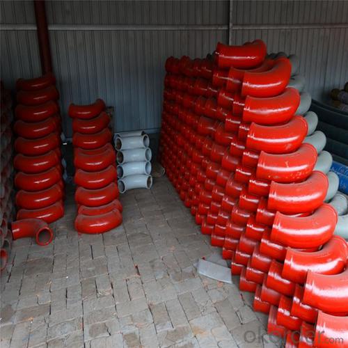
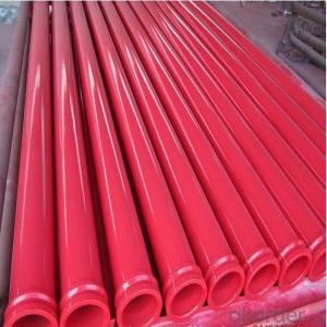
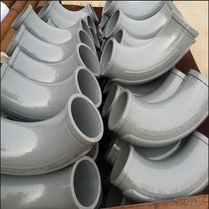
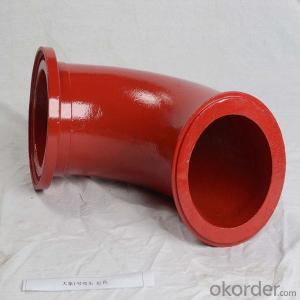
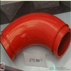
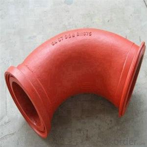
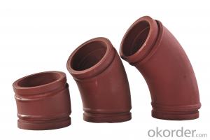
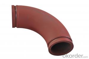
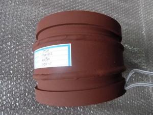
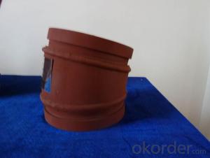
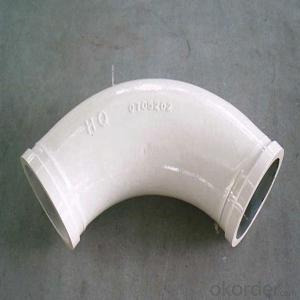
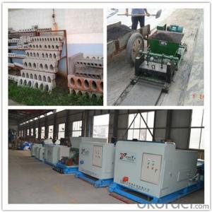
DN125X R275 45D Double Wall Truck Mounted Concrete Pump Elbow
- Ref Price:
-

- Loading Port:
- China Main Port
- Payment Terms:
- TT OR LC
- Min Order Qty:
- -
- Supply Capability:
- -
OKorder Service Pledge
OKorder Financial Service
You Might Also Like
Product parameters:
Name | Material | Specification | Weight | Common life time | Life tine for two end parts | Max work pressure |
Normal bend | ZG40Mn2 | DN125R27590° | 16kgs | 6000-8000m³ | 1000-3000m³ | 126 bar |
Wear-resistant bend | Mn13-4 | DN125R27590° | 16.5kgs | 20000-25000m³ | 2000-7000m³ | 132 bar |
Twin wall bend | Cr20NiCu1Mo+G20 | DN125R27590° | 15kgs | 60000-80000m³ | 20000-30000m³ | 91 bar |
Twin wall bend | GX350+G20 | DN125R27590° | 15kgs | 80000-150000m³ | 40000-50000m³ | 98 bar |


Product Specifications Model:


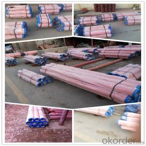
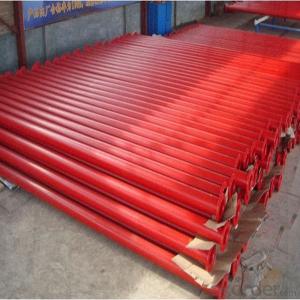
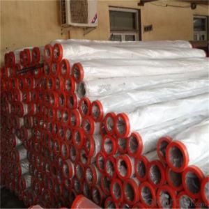
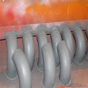
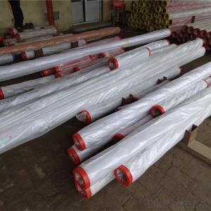
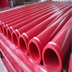
Packaging and transport:
No.1 Export standard packing
No.2 Seaworthy packing
No.3 other ways or according to the customer demand

Why choose us:
1. We are a comprehensive manufacturing and trading company.
2. Our company is one of the biggest manufacturing and trading companies in China.
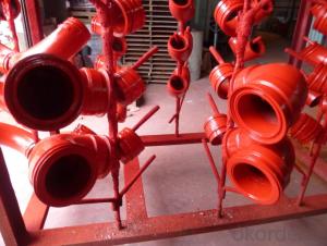
3. We have been specialized in producing concrete pump spare parts for 10 years and specialized in producing all kinds of concrete pump parts. As Concrete Pump Pipe, Concrete Pump Elbow, Concrete Pump Rubber Hose, Concrete Pump Wear Plate, Concrete Pump S Valve, Concrete Pump Piston and so on.
4. We are famous for our superior quality, competitive prices, first-class craftworks, safe package and prompt delivery.
5. We have been supplying concrete pump parts for SCHWING, PUTZMEISTER, SANY, CIFA, KYOKUTO, ZOOMLION for 10 years, so we can promise you the quality and best price.
- Q: How to design the common mechanical parts with CATIA, and how to solve the problem when the units are inconsistent?
- Very simple. Write the value / conversion value of the drawing in the parameter
- Q: What are the main functions of CAE software commonly used in the design of mechanical products or parts?
- Strength, stiffness, modal analysis, structural optimization, and so on
- Q: I am engaged in the mechanical design work, asks the three-dimensional mechanical component model to download the website.
- 3D resource network, standard parts library, community resource library are all free. Most of the members can see and download it. No charge after registration.
- Q: And parts, components, institutions, the relationship between the threeIs the key a part?
- parts, but to "the pedals and sprocket" together, and form component. Several components constitute a chain drive mechanism. Similarly, key parts.
- Q: In mechanical design, what is the significance of drawing 3D drawings?.
- Product design is to determine the shape of the product and product function, but also the decisionThe most important part of the product quality, the product design work on the cost of the product alsoPlay a vital role. With the continuous development of computers, CAD technology is consideredComputer aided design has become an indispensable tool for designers. CAD technology is moving from 2D CAD to 3D CAD.Three dimensional design software, engineering and productionAnalysis, calculation, geometry modeling, simulation and experiment, drawing graphics and engineering numbersAccording to library management, generate design documents and other functions. 3D CADTechnology was born toIt has been widely used in the fields of machinery, electronics, architecture, chemical engineering, aeronautics and AstronauticsAnd energy, transportation and other fields, the design efficiency of products has been improved rapidly. Our country CADTechnical research,Great progress has been made in development and popularization,Product designComplete two-dimensional CADThe popularization of technology has ended the history of hand drawing,It has played an obvious role in reducing the intensity of manual labor and improving the economic efficiency.Advantages of 3D design software2.1.1Solid modeling of parts2.1.2The product is easy to modify2.1.3Generating entity assembly drawingTwo point twomouldCAD/CAMIntegrated manufacturingTwo point threeMechanicsCAEFunction application
- Q: Why do the design of mechanical parts (flanges and elbows) be based on the yield limit?
- In order to reach the yield limit, it is the failure of the material to begin the elasticity, and the elastic-plastic stage has been started. This is designed according to GB150-1998. You can look at the analysis data of the blasting process of the steel
- Q: The basic idea of mechanical parts design is briefly introduced
- 1, according to the requirements and conditions, determine the type of parts2, determine the parts load, select materials, formulate parts work capacity, calculate the key size;
- Q: Before listening to the teacher mentioned that, when the design of components, we should take into account the actual processing capacity of the factory, and some look very simple things, the factory is unable to process! I want to know what the reason is!!!
- The key is and plant equipment and the level of the workers, such as some complex tooling, laser cutting or five axis machining center type of equipment can be processed, it needs to consider the economic.Another example is that the suspension part of mark 206 has a part, but if the layman sees a simple shaft type parts, it can not be nationalized, because its precision requirements are too high and can only be imported, and so on
- Q: Are there any standards or specifications for the design of parts list in mechanical design?
- Each company's specifications are not the same, but the general processing parts must have part name, parts drawing number, quantity, material / heat treatment methods (surface treatment methods), remarks, etc.. If purchased, it includes name, model, brand, requirement, remark and so on
- Q: In the process of mechanical design, those areas should be designed as fillet and when to design chamfer. These materials can be found in those places, and the title of the book is also OK. Thank you!
- The edges of the non machined surfaces of various castings shall be designed as arc R, and the sharp edge of the lathe shall be chamfered 45 degrees. These are in the design manual, you are new, and when you are free, look at the design manual.
Send your message to us
DN125X R275 45D Double Wall Truck Mounted Concrete Pump Elbow
- Ref Price:
-
- Loading Port:
- China Main Port
- Payment Terms:
- TT OR LC
- Min Order Qty:
- -
- Supply Capability:
- -
OKorder Service Pledge
OKorder Financial Service
Similar products
Hot products
Hot Searches

