China Best Selling VFD Frequency Drive Three phase 380V
- Ref Price:
-

- Loading Port:
- Tianjin
- Payment Terms:
- TT OR LC
- Min Order Qty:
- 1 pc
- Supply Capability:
- 100000 pc/month
OKorder Service Pledge
OKorder Financial Service
You Might Also Like


Specifications
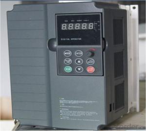
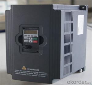
1.220V Single Phase Variable Frequency Drive 2.2KW
2.Advanced control technology
3.Easy to operate
220V Single Phase Variable Frequency Drive 2.2KW
General
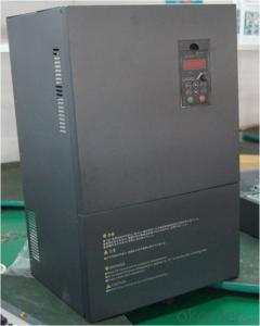
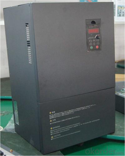
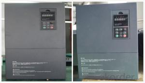
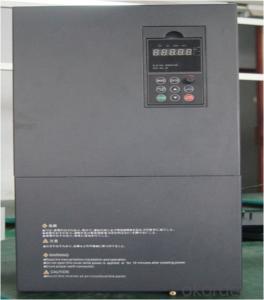
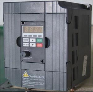
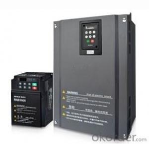
CNBM frequency inverter is a high-quality, multi-function,
low-noise variable frequency drive which is designed, developed and manufactured according to international standards.
It can meet different needs of industrial conditions.
The inverter applies advanced control technology of space voltage vector PWM, with functions of constant voltage control, power-off restart, dead zone compensation, automatic torque compensation, online modification parameter, high-speed impulse input, simple PLC and traverse.

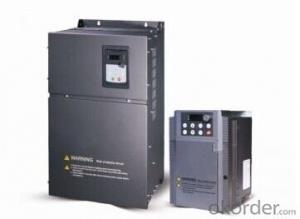
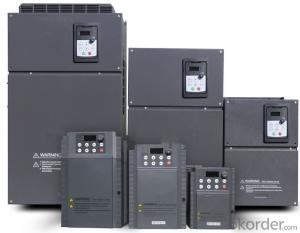
Product Name:CMAX-VCG15/P18.5T3 ~ CMAX-VCG18.5/P22T3
Application
Textile: coarse spinner, spinning frame, wrap-knitting machine, loom, knitting machine, silk-spinning machine, etc.
Plastic: extruder, hauling machine, decorating machine, etc.
Pharmacy: mixer, roaster, etc.
Woodworking: engraving machine, sander, veneer peeling lathe, etc.
Papermaking: single type papermaking machine, etc.
Machine tool: non-core grinding machine, optical lens grinding machine, cutting mill, etc.
Printing: cloth-washing machine, dye vat, etc.
Cement: feeder, air blower, rotary furnace, mixer, crusher, etc
Fan and pump: kinds of fans, blowers and pumps
Specification
Item | Specification | |
Input | Input voltage | 220/380V±15% |
Input frequency | 47~63Hz | |
Output | Output voltage | 0~input voltage |
Output frequency | 0~600Hz | |
Peripheral interface characteristics | Programmable digital input | 4 switch input, 1 high-speed impulse input |
Programmable analog input | AI1: 0~10V input AI2: 0~10V input or 0~20mA input, | |
Programmable open collector output | 2 Output (3.7kW and above: 1 Open collector output) | |
Relay Output | 1 Output (3.7kW and above: 2 Relay output) | |
Analog output | 2 Output, one is 0~10V, another is 0~20mA or 0~10V | |
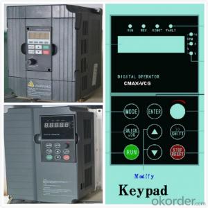
Keypad | Display:5-digit 8-section LED (Red), 2 indicators; parameter setting: 8 keys (including multi-function hot key ), 1 potentiometer | |
Technical performance characteristics | Control mode | All digital space voltage vector SVPWM algorism |
Overload capacity | G purpose: 150% rated current 60s P purpose: 120% rated current 60s | |
Speed ratio | 1: 100 | |
Carrier frequency | 1.0~10.0kHz | |
Torque compensation | Linear, multi-point, 1.3th power, 1.7th power, 2.0th power reduced torque; Compensation voltage range: automatic compensation and manual compensation 0.1~10% | |
Automatic voltage adjustment | It can automatically maintain output voltage constant when grid voltage fluctuates. | |
Automatic current adjustment | When the current is over current limit, under clocking automatically limits output current. | |
Function characteristics | Frequency setting mode | Keypad digital analog input, keypad potentiometer, impulse frequency, communication, multi-step speed and simple PLC, PID setting and so on, switch-over of setting modes. |
Simple PLC, multi-step speed control | 16-step speed control | |
Special function | Traverse control, length control, time control | |
QUICK/JOG key | User-defined multi-function hot key | |
Protection function | Over-current, Over voltage, under-voltage, over-heat, phase failure, over-load and motor over-load | |
Working condition | Installation site | Indoor, altitude of less than 1km, dust free, non-corrosive gases, no direct sunlight |
Application environment | -10°C~+40°C, 20~90%RH (no dew) | |
Vibration | Less than 0.5g | |
Storage temperature | -25°C~+65°C | |
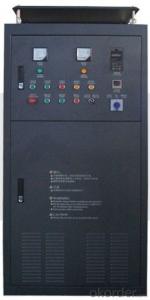
Installation type | Wall-mounted type, floor cabinet type | |
Cooling mode | Air-forced cooling | |
- Q: How does the frequency converter fit the brake unit and the brake resistor?!
- To calculate how much energy consumption, can be converted into electric current, to select the brake unit. You can also choose the braking resistance (to consider resistance temperature characteristics to choose), then select the brake unit with matching (see manufacturer manual).
- Q: When the inverter is running at full 50HZ, the output voltage decreases and the output current becomes smaller. What is the reason?
- I don't know if you're a manufacturer of car gearboxes, and we've also done car engine tests. The operation in the 50HZ when the inverter is not reduced voltage, if only a little decrease will decrease, this is due to increasing frequency, controllable silicon resistance increases, the corresponding motor voltage decreased slightly, not what the essence of influence.
- Q: Which country invented the inverter?
- There are two kinds of PFC, one is passive PFC (also called passive PFC), and the other is active PFC (also called active PFC). Passive PFC generally uses the inductance compensation method for the phase between the fundamental voltage and current of the AC input is decreased to improve the power factor, but the passive power factor PFC is not very high, can reach 0.7~0.8; PFC by active inductor and capacitor and electronic components, small size, power factor could be very high, but the cost is higher a passive PFC.
- Q: It was when processing a workpiece, processing spindle stops suddenly (other are normal) a check is, I jump out of the inverter, I can click on a processing, and then processing not long after they happen, (do not open the machine spindle machining will also be the case)
- It should be a frequency converter. Right now, look at the frequency converter output frequency settings, tune, and suggest the next election wide output frequency converter, or simply PLC
- Q: What is the main function of the frequency converter on the machine tools?
- Where is the difference between soft starter and converter?
- Q: 5.5KW frequency converter with 4.5KW deep water pump, pressure regulator by conveying signal to frequency converter start normal, the pressure to reduce the frequency converter after the start, to about 30Hz in order to maintain the pressure about shocks, 30 seconds inverter over-current alarm. Can it be the fault of the frequency converter? How should I check it?
- Once the inverter has hardware faults, such as rectifier, inverter circuit and so on. The IGBT module may be damaged, and most of the time it will damage the drive components. The most easily damaged devices are the regulator and the optocoupler. Conversely, components such as capacitance, leakage, breakdown, and optocoupler aging can also cause IGBT modules to burn out or frequency conversion, and output voltage is unbalanced. Check if there is a problem with the drive circuit, and compare the resistance of the trigger terminals when the circuit is not switched on. The voltage waveform at the trigger end can be measured when the power is switched on. However, some inverters are not equipped with modules and can not switch on, when the module P end of the series into a false load, to prevent detection, mistakenly touch the originator or other circuit burned module. In this case, the frequency converter has been seriously damaged (by measuring whether the input and output are short circuited), then there should be special technical personnel maintenance, and generally may not re energized, so as not to expand the scope of failure.
- Q: Heating inverter commissioning steps
- And carry on the test run 1. manual operation of the frequency converter panel running stop, observe the motor running process and the frequency converter display window, to see if there is abnormal phenomenon. 2. if the P is started and the over-current protection is stopped in the motor, the acceleration P deceleration time should be reset. The acceleration of the motor during acceleration and deceleration depends on the acceleration torque, while the frequency change rate of the inverter during the start and braking is set by the user. If the inertia of motor or motor load change, speed or deceleration rate according to frequency change preset when possible acceleration torque is not enough, resulting in motor stall, motor speed and the inverter output frequency coordination, thus causing overcurrent or overvoltage. Therefore, it is necessary to set acceleration and deceleration time according to the inertia and load of the motor, so that the frequency change rate of the converter can be coordinated with the speed change rate of the motor.
- Q: I would like to ask, the inverter in use in the grid is very high?
- In the process of using frequency converter, the demand for voltage fluctuation of power grid is not high. It depends on what brand of transducer. As a result, most of the grid voltage can meet the requirements, except in rural or remote areas where voltage changes exceed their permissible values. In addition, the frequency converter on the power grid harmonics also have requirements, if the harmonic content of more than 20%, will lead to frequency converter misoperation, false alarm, more serious circumstances, will lead to inverter out of control, or damage. However, most of the current harmonics will not happen, unless a large number of individual factories use frequency converters, servo, intermediate frequency furnace, welding machine and other equipment.
- Q: Can a power converter be used in a motor with small power? Will it burn the motor?
- Yes, but you have to set some parameters that correspond to changes in the motor to play a protective role
- Q: What is the main harmonic produced by a transducer? How about the degree?
- From the structure point of view, the inverter can be divided into indirect frequency conversion and direct frequency conversion of two major categories. The indirect frequency conversion turns the power frequency current into DC through the rectifier, and then converts the DC to the controllable frequency AC through the converter. The direct frequency converter transforms the power frequency exchange into the controllable frequency exchange, without the intermediate direct current link. Each phase is a reversible circuit in which two thyristor rectifier devices are antiparallel. The two groups of positive and negative switches are switched by a certain period, and the alternating voltage is gained on the load. The amplitude of the U0 is decided by the control angle of each rectifier device, and the frequency is determined by the switching frequency of the two sets of rectifier devices, and the frequency of the U0 is determined by the switching frequency of each rectifier unit. At present, more or more inter frequency converter.
Send your message to us
China Best Selling VFD Frequency Drive Three phase 380V
- Ref Price:
-
- Loading Port:
- Tianjin
- Payment Terms:
- TT OR LC
- Min Order Qty:
- 1 pc
- Supply Capability:
- 100000 pc/month
OKorder Service Pledge
OKorder Financial Service
Similar products
Hot products


Hot Searches

