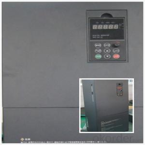
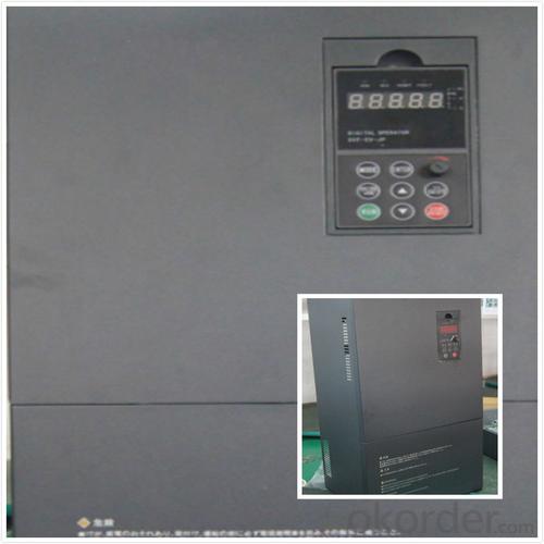
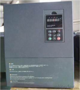
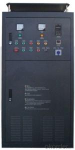
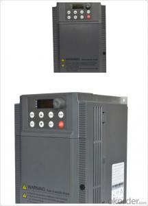
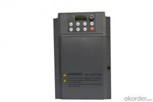
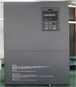
China Best Selling VFD Frequency Drive 3 phase 380V 15kw
- Ref Price:
-

- Loading Port:
- Tianjin
- Payment Terms:
- TT OR LC
- Min Order Qty:
- 1 pc
- Supply Capability:
- 100000 pc/month
OKorder Service Pledge
OKorder Financial Service
You Might Also Like

Specifications
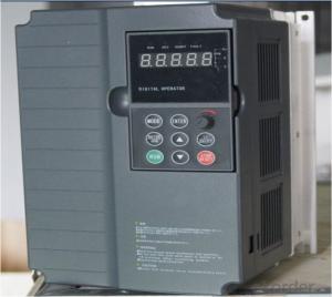
1.220V Single Phase Variable Frequency Drive 2.2KW
2.Advanced control technology
3.Easy to operate
220V Single Phase Variable Frequency Drive 2.2KW
General
CNBM frequency inverter is a high-quality, multi-function,
low-noise variable frequency drive which is designed, developed and manufactured according to international standards.
It can meet different needs of industrial conditions.
The inverter applies advanced control technology of space voltage vector PWM, with functions of constant voltage control, power-off restart, dead zone compensation, automatic torque compensation, online modification parameter, high-speed impulse input, simple PLC and traverse.
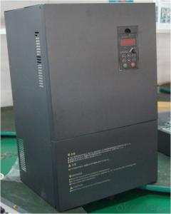
Product Name:CMAX-VCG15/P18.5T3 ~ CMAX-VCG18.5/P22T3
Application
Textile: coarse spinner, spinning frame, wrap-knitting machine, loom, knitting machine, silk-spinning machine, etc.
Plastic: extruder, hauling machine, decorating machine, etc.
Pharmacy: mixer, roaster, etc.
Woodworking: engraving machine, sander, veneer peeling lathe, etc.
Papermaking: single type papermaking machine, etc.
Machine tool: non-core grinding machine, optical lens grinding machine, cutting mill, etc.
Printing: cloth-washing machine, dye vat, etc.
Cement: feeder, air blower, rotary furnace, mixer, crusher, etc
Fan and pump: kinds of fans, blowers and pumps
Specification
Item | Specification | |
Input | Input voltage | 220/380V±15% |
Input frequency | 47~63Hz | |
Output | Output voltage | 0~input voltage |
Output frequency | 0~600Hz | |
Peripheral interface characteristics | Programmable digital input | 4 switch input, 1 high-speed impulse input |
Programmable analog input | AI1: 0~10V input AI2: 0~10V input or 0~20mA input, | |
Programmable open collector output | 2 Output (3.7kW and above: 1 Open collector output) | |
Relay Output | 1 Output (3.7kW and above: 2 Relay output) | |
Analog output | 2 Output, one is 0~10V, another is 0~20mA or 0~10V | |
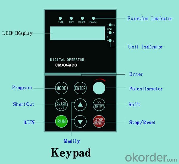
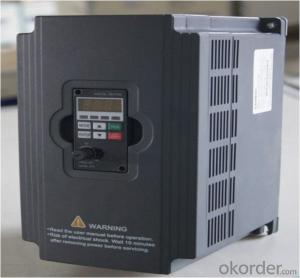
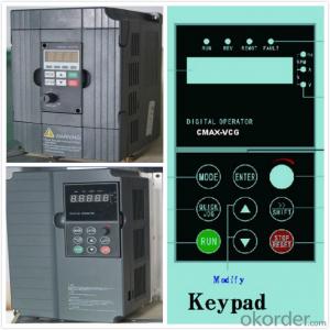
Keypad | Display:5-digit 8-section LED (Red), 2 indicators; parameter setting: 8 keys (including multi-function hot key ), 1 potentiometer | |
Technical performance characteristics | Control mode | All digital space voltage vector SVPWM algorism |
Overload capacity | G purpose: 150% rated current 60s P purpose: 120% rated current 60s | |
Speed ratio | 1: 100 | |
Carrier frequency | 1.0~10.0kHz | |
Torque compensation | Linear, multi-point, 1.3th power, 1.7th power, 2.0th power reduced torque; Compensation voltage range: automatic compensation and manual compensation 0.1~10% | |
Automatic voltage adjustment | It can automatically maintain output voltage constant when grid voltage fluctuates. | |
Automatic current adjustment | When the current is over current limit, under clocking automatically limits output current. | |
Function characteristics | Frequency setting mode | Keypad digital analog input, keypad potentiometer, impulse frequency, communication, multi-step speed and simple PLC, PID setting and so on, switch-over of setting modes. |
Simple PLC, multi-step speed control | 16-step speed control | |
Special function | Traverse control, length control, time control | |
QUICK/JOG key | User-defined multi-function hot key | |
Protection function | Over-current, Over voltage, under-voltage, over-heat, phase failure, over-load and motor over-load | |
Working condition | Installation site | Indoor, altitude of less than 1km, dust free, non-corrosive gases, no direct sunlight |
Application environment | -10°C~+40°C, 20~90%RH (no dew) | |
Vibration | Less than 0.5g | |
Storage temperature | -25°C~+65°C | |
Installation type | Wall-mounted type, floor cabinet type | |
Cooling mode | Air-forced cooling | |
- Q: High-voltage converterGeneral inverterPump frequency converterEngineering frequency converterCould you tell me some frequency converter according to the class?
- According to the classification of link Transformation: (1) the AC-DC-AC converter is the first AC into DC rectifier through, and then transformed into the frequency DC voltage adjustable AC inverter, also known as indirect, is currently widely used general-purpose inverter. (2) can be divided into cycloconverter, is directly converted into AC voltage adjustable frequency AC, also known as direct inverter DC power supply according to the classification of properties: (1) the voltage type inverter voltage type inverter is characteristic of DC link energy storage device using a large capacitor load reactive power will be it is to buffer the DC voltage, DC power supply is relatively stable, smaller internal resistance and the equivalent voltage source, so that the voltage type inverter, are often used for load voltage changes in the larger situation. (2) current inverter current type inverter is characterized by large DC link inductance as a storage buffer of reactive power, which changes the current control, the voltage is close to sine wave, because the DC resistance is large, so that the current source converter (current). The characteristics of current source inverter (advantages) can restrain the load current is frequent and rapid changes.
- Q: The functions of frequency converter and UPS are similar, especially the power frequency UPS?
- Frequency converter is the application of frequency conversion technology and micro electronics technology, by changing the power supply frequency of the motor to control AC motor power control equipment. The frequency converter is mainly composed of rectifier (AC DC converter), filter, inverter (DC AC converter), brake unit, drive unit, detection unit, micro processing unit and so on. Inverter by internal IGBT drive voltage and frequency off to adjust the output power, the power supply voltage required to provide according to the actual needs of the motor, so as to achieve the purpose of speed, energy saving, in addition, there are a lot of protection drive, such as over-current, over-voltage, overload protection and so on. With the continuous improvement of the degree of industrial automation, inverter has also been widely used.UPS is an uninterruptible power supply, including an energy storage device, a rectifier, inverter as the main component of the regulator, frequency stabilized AC power supply. The main use of battery energy storage power supply device to provide uninterrupted computer / server, storage equipment, network equipment, computer communication network system and industrial control system, need continuous operation of industrial equipment in power outages. When the power input is normal, UPS electric voltage supplied to the load, the UPS is an AC electric regulator, it is also to the storage device such as a battery charging; when the power interruption (outage), UPS immediately to the storage device (such as batteries or fly wheel the electric energy storage system), continue to supply alternating current to the load by the method of inverse transformation, the load to maintain normal working and protect the load of software and hardware is not damaged.
- Q: What is frequency conversion? What is the function of frequency converter?
- Soft start energy-saving1: Motor hard start a serious impact on the power grid, but also on the power grid capacity is too high, damage to the baffle and valve high current and vibration generated when starting the great of equipment, is extremely detrimental to the life line. While the use of variable frequency energy saving device, using the frequency converter soft start function will start the current starting from zero, will not exceed the maximum rated current, the impact on power loss and the power supply capacity to prolong the service life of equipment and valves. It saves the maintenance cost of equipment.
- Q: There is a feed and send system. Now due to the severity of the material is not the same as the two converters often change speed, the workers do not understand their own, often by, often bad now how to use the best way you can use a potentiometer or other method, control of the two frequency converter, synchronous operation. Is to adjust one, and the other also with the kind of frequency, so that you can let the workers themselves to open, and the two inverters, the same manufacturer, the same model, the same load,
- Two start with frequency conversion. The frequency converter is controlled by a potentiometer, and the analog output signal (AO.GND) is sent into the converter and connected to the AI.GND port of the converter. If the pulse port can also be connected to the pulse port.
- Q: How do you understand the ramp up (descent) time of the inverter? Thank you!
- The ramp up time is to start from the 0 speed, inverter, running to reach the given speed (for example: 1420) the time required, in general, the longer the time, the frequency converter and motor impact is small. In the actual work process, according to process requirements to set the length of time. (more than 10-15 seconds) or so, if it is a pump or fan motor, do not need to change its rise time, the default can.
- Q: What is the upper and lower limit of the environmental temperature to ensure the normal operation of the inverter?
- Inverter environment temperature(1) working temperature. The use of frequency converter should pay attention to the environmental matters, the internal is high-power electronic components, is easily affected by the operating temperature, the product is generally required to be 0~55 degrees, but in order to ensure safe and reliable work, when usedShould be considered under the best control in 40 DEG C. In the control box, the inverter shall be installed on the upper part of the box, and strictly comply with the installation requirements of the product manual, absolutely not allowed to sendA heat element or a heat generating element is mounted close to the bottom of the inverter.
- Q: What is the difference between inverter energy consumption braking and motor energy consumption braking?
- A direct current is generated in the stator winding so that a fixed magnetic field is generated. At this point, the rotor cuts the magnetic field lines in the direction of rotation, resulting in a braking torque. Because the braking method is not like regenerative braking (using frequency converter), the energy generated by braking is fed back to the grid, but the energy is dissipated by the motor alone, so it is called energy consumption braking. The utility model is also used for braking by direct current in the stator winding, so the energy consumption braking is called DC injection braking. By using the backward switch Q to return the point voltage back to the grid, the armature current will become a copy, and the current will be of the same magnitude, resulting in a great braking torque of the motor, which will stop the motor.
- Q: How to maintain the frequency converter will not damage, or regular maintenance?
- 1. cooling fan, inverter power module is the most serious heating device, the continuous heat generated by the work must be promptly discharged, the general fan life of about 10Kh-40Kh. According to the continuous operation of converter for 2-3 years, it is necessary to replace the fan2. filter capacitor, intermediate circuit filter capacitor: also called electrolytic capacitor, its main function is to smooth the DC voltage, absorb the low-frequency harmonic in dc.
- Q: I would like to ask, the inverter in use in the grid is very high?
- In the process of using frequency converter, the demand for voltage fluctuation of power grid is not high. It depends on what brand of transducer. As a result, most of the grid voltage can meet the requirements, except in rural or remote areas where voltage changes exceed their permissible values. In addition, the frequency converter on the power grid harmonics also have requirements, if the harmonic content of more than 20%, will lead to frequency converter misoperation, false alarm, more serious circumstances, will lead to inverter out of control, or damage. However, most of the current harmonics will not happen, unless a large number of individual factories use frequency converters, servo, intermediate frequency furnace, welding machine and other equipment.
- Q: How do you set the frequency with panels?. What are the specific steps?
- The parameter 700 is the starting signal, the 1 is a panel key starting, and the 2 is an external signal starting;The parameter 1000 is the frequency setting value, and the 1 is a panel lifting key, and the frequency is changed, and 2 is changed by the external analog signal.Your problem, the start signal is set up, finished, the parameter 1000 should be 1, so that the panel set frequency, and then set the parameter 1031 to 1, so that it automatically save the frequency changes after the value
Send your message to us
China Best Selling VFD Frequency Drive 3 phase 380V 15kw
- Ref Price:
-
- Loading Port:
- Tianjin
- Payment Terms:
- TT OR LC
- Min Order Qty:
- 1 pc
- Supply Capability:
- 100000 pc/month
OKorder Service Pledge
OKorder Financial Service
Similar products


Hot products

Hot Searches
Related keywords

