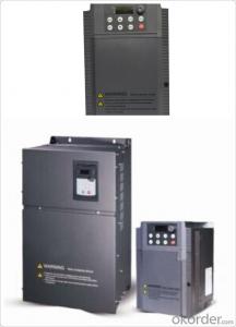
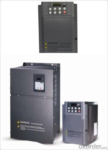
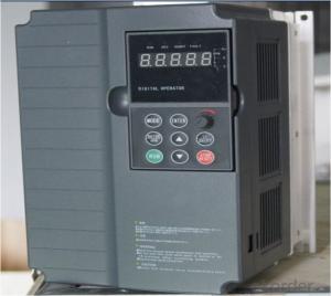
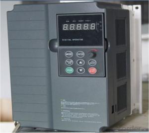
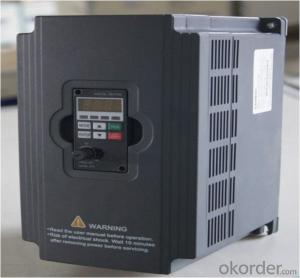
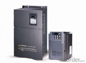
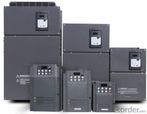
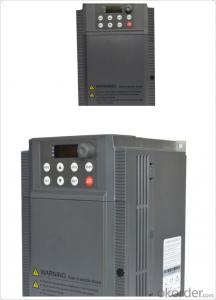
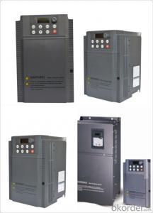
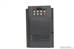
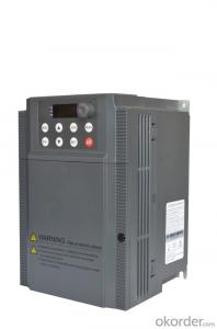
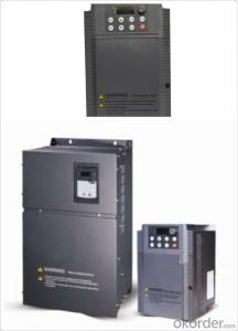
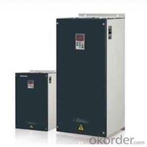
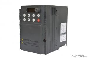
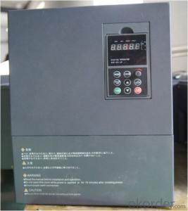
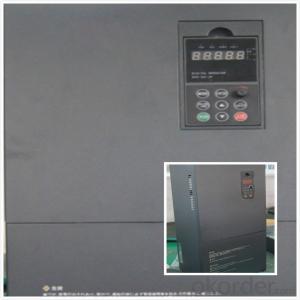
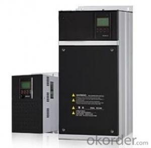
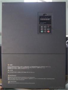
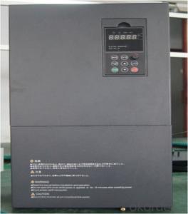
Frequency Inverter Single-phase 220V class 5.5KW
- Loading Port:
- Tianjin
- Payment Terms:
- TT OR LC
- Min Order Qty:
- 1 pc
- Supply Capability:
- 100000 pc/month
OKorder Service Pledge
OKorder Financial Service
You Might Also Like
General
CNBM frequency inverter is a high-quality, multi-function,
low-noise variable frequency drive which is designed, developed and manufactured according to international standards.
It can meet different needs of industrial conditions.
The inverter applies advanced control technology of space voltage vector PWM, with functions of constant voltage control, power-off restart, dead zone compensation, automatic torque compensation, online modification parameter, high-speed impulse input, simple PLC and traverse.
Application
Textile: coarse spinner, spinning frame, wrap-knitting machine, loom, knitting machine, silk-spinning machine, etc.
Plastic: extruder, hauling machine, decorating machine, etc.
Pharmacy: mixer, roaster, etc.
Woodworking: engraving machine, sander, veneer peeling lathe, etc.
Papermaking: single type papermaking machine, etc.
Machine tool: non-core grinding machine, optical lens grinding machine, cutting mill, etc.
Printing: cloth-washing machine, dye vat, etc.
Cement: feeder, air blower, rotary furnace, mixer, crusher, etc
Fan and pump: kinds of fans, blowers and pumps
Specification
Item | Specification | |
Input | Input voltage | 220/380V±15% |
Input frequency | 47~63Hz | |
Output | Output voltage | 0~input voltage |
Output frequency | 0~600Hz | |
Peripheral interface characteristics | Programmable digital input | 4 switch input, 1 high-speed impulse input |
Programmable analog input | AI1: 0~10V input AI2: 0~10V input or 0~20mA input, | |
Programmable open collector output | 2 Output (3.7kW and above: 1 Open collector output) | |
Relay Output | 1 Output (3.7kW and above: 2 Relay output) | |
Analog output | 2 Output, one is 0~10V, another is 0~20mA or 0~10V | |
Keypad | Display:5-digit 8-section LED (Red), 2 indicators; parameter setting: 8 keys (including multi-function hot key ), 1 potentiometer | |
Technical performance characteristics | Control mode | All digital space voltage vector SVPWM algorism |
Overload capacity | G purpose: 150% rated current 60s P purpose: 120% rated current 60s | |
Speed ratio | 1: 100 | |
Carrier frequency | 1.0~10.0kHz | |
Torque compensation | Linear, multi-point, 1.3th power, 1.7th power, 2.0th power reduced torque; Compensation voltage range: automatic compensation and manual compensation 0.1~10% | |
Automatic voltage adjustment | It can automatically maintain output voltage constant when grid voltage fluctuates. | |
Automatic current adjustment | When the current is over current limit, under clocking automatically limits output current. | |
Function characteristics | Frequency setting mode | Keypad digital analog input, keypad potentiometer, impulse frequency, communication, multi-step speed and simple PLC, PID setting and so on, switch-over of setting modes. |
Simple PLC, multi-step speed control | 16-step speed control | |
Special function | Traverse control, length control, time control | |
QUICK/JOG key | User-defined multi-function hot key | |
Protection function | Over-current, Over voltage, under-voltage, over-heat, phase failure, over-load and motor over-load | |
Working condition | Installation site | Indoor, altitude of less than 1km, dust free, non-corrosive gases, no direct sunlight |
Application environment | -10°C~+40°C, 20~90%RH (no dew) | |
Vibration | Less than 0.5g | |
Storage temperature | -25°C~+65°C | |
Installation type | Wall-mounted type, floor cabinet type | |
Cooling mode | Air-forced cooling | |
- Q: What's the use of switching frequency of converter?
- Meanwhile, the switching frequency of the converter is adjusted, and the power loss can be adjusted. Because the switching frequency of power loss and inverter power module IGBT is related with the increase in switching frequency inverter and increasing the power loss, this makes the efficiency drop, two is the power module heating increases, is detrimental to the operation, of course work electric converter pressure is high, the power loss also increase effect.
- Q: What does a frequency converter do?
- Mainly used to drive AC motors, AC motors to achieve stepless speed regulation.For example, for the fan, with frequency converter to adjust the speed of the motor speed, you can change the size of the air supply.There are many occasions that need speed regulation. Using frequency converter to speed up is simple and energy-saving.
- Q: How does the frequency converter change the voltage and change the speed of the motor?
- The frequency converter regulates the speed of the motor, mainly by changing the frequency. The frequency determines the synchronous speed of the motor, and the speed of the motor can be lowered by reducing the frequency.
- Q: I am in control of the equipment: the same mechanical movement, this needs a motor drive, a frequency converter drive. Now it's due to the mechanical location: buy two units of the same motor. Can you use a converter in parallel to drive it? Please point out! Thank you (frequency converter: the power of Schneider is equal to the sum of two motors)
- Can be controlled at the same time, but the power of the inverter is equal to the sum of the power of the two motors multiplied by 1.2 times before you can. And the inverter output can not add contactor. To ensure that the inverter is to control the start and stop of the two motors.
- Q: What are the precautions for frequency converter wiring installation?
- 1, between the power supply and inverter, access to low-voltage circuit breaker and contactor, protection of frequency converter and easy installation and maintenance;2, frequency converter and motor are generally not allowed to access contactor;3, frequency converter generally does not need to meet the thermal relay;4, the output side of the inverter is not allowed to connect capacitors and capacitive single-phase motors.5, the surrounding pay attention to ventilation, dust-proof6, the power input line has sufficient area, the screws tighten as far as possible, but do not slip, you can refer to the specifications torque.7, connect the motor cable as short as possible, there are computer occasions, as far as possible shielded cable8, the control signal line should not parallel to the power line. If parallel must be used, the shielding line and one end of the earth will be used.9, use 485 or 232 communication to wear a magnetic ring, and use twisted pair.
- Q: What does the RUN key on the inverter mean? How do you use it?
- According to the actual needs of the motor to provide the required power supply voltage, and then to achieve energy saving, speed control purposes, in addition, there are many inverter protection functions, such as over-current, overvoltage, overload protection, etc.. With the continuous improvement of the degree of industrial automation, inverter has also been widely used.
- Q: How to deal with the fault Yaskawa inverter GF
- Inverter display "GF" fault information for ground fault (i.e. the output current exceeds the rated current of the inverter 50%), a power module is reported for G5 damage, may also be a driving circuit, running the report "GF" (the external load is a good case), G5 is PC929 damage. With current detection circuit,
- Q: What is the difference between SIEMENS inverter and built-in filter?
- There is no built-in filter converter in the price slightly lower, mainly used in the equipment efficiency (power factor) requirements are not high, anti-interference ability requirements are not strict place;The frequency difference with built-in filter is mainly to the requirements of different electrical parameters in specially designed, can improve equipment (power factor), has the good anti-interference ability, prevent the transient surge of inverter module impact, has a good protective effect.
- Q: What are the possible causes of frequency hopping overload?
- The meaning of inverter overload protection is that the output current of the inverter continues to exceed the rated current, but it has not exceeded the transient flow point, and the general duration is defined as 1min. The general overload constant torque converter is 150% 1min, variable torque converter is generally 110%120%/1min.
- Q: What is the difference between inverter energy consumption braking and motor energy consumption braking?
- When the motor is disconnected from the power supply, in order to make the motor stop quickly, using the power control method in motor power supply coupled with the normal operation of power supply phase at this time, the direction of rotation of the rotation direction of the motor rotor and the motor rotating magnetic field in electromagnetic force at the moment is generated by the motor brake torque, motor speed reducer. Using the Q switch voltage at both ends of the armature is disconnected from the power grid, and it will immediately receive a braking resistor RL, at this time, the main magnetic field in the motor armature remains unchanged, the cause inertia continues to rotate the torque braking torque, the motor speed down, until the stop.
Send your message to us
Frequency Inverter Single-phase 220V class 5.5KW
- Loading Port:
- Tianjin
- Payment Terms:
- TT OR LC
- Min Order Qty:
- 1 pc
- Supply Capability:
- 100000 pc/month
OKorder Service Pledge
OKorder Financial Service
Similar products
Hot products
Hot Searches
Related keywords
