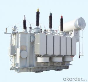
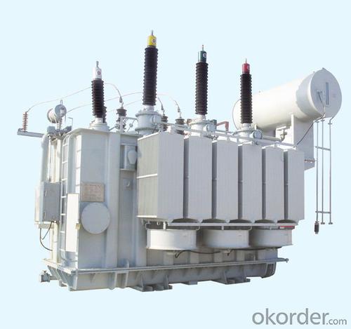
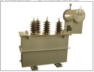
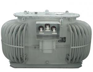
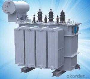
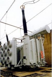
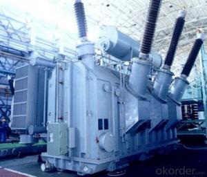
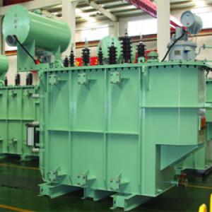
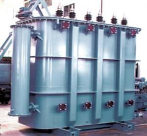
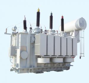
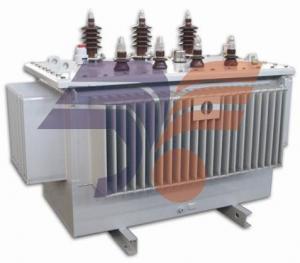
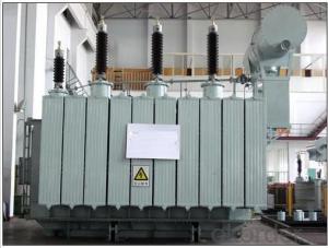
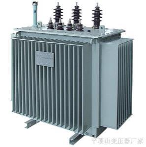
SZ9 ON-load Tap-changer Power Transformer
- Loading Port:
- Shanghai
- Payment Terms:
- TT OR LC
- Min Order Qty:
- -
- Supply Capability:
- 1000sets set/month
OKorder Service Pledge
Quality Product, Order Online Tracking, Timely Delivery
OKorder Financial Service
Credit Rating, Credit Services, Credit Purchasing
You Might Also Like
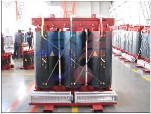
1.Product Feature The sz9 on-load tap-changer power transformer is widely applies to urban and rural electric network construetion. The iron core is in ladder shape and changes the traditional piling way of iron core as well as the inner distribution of magnetic way. It also decrease the no-load consurmption, no-load current consurmption and noise pollution all by 20%. The new product applies CAD tool and marked with advanced design, reasonable structure, high quality material. It accords with GB1094-1996 and GB/T64511999. 2.Technical Specification
| |||||||||||||||||||||||||||||||||||||||||||||||||||||||||||||||||||||||||||||||||||||||||||||||||||||||||||||||||||||||||||||||||||||||||||||||||||||||||||||
- Q: A want to know what happens to transformer when it is overloaded. Where i can get information about this
- A transformer is just like any other circuit. The only difference is the primary of the transformer induces a current and voltage in the secondary without a direct electrical connection. But the induction comes from the collapse of the magnetic field in the primary which induces a current in the secondary. That current generated in the secondary follows the same laws as any other circuit. If you overload those terminal wires or short circuit it it will overheat and melt the wires possibly if you don't have it fused protected. In fact they make induction furnaces which are just transformers with the secondary that forms a short circuit in the coil. The temperature gets hot enough to melt iron and non-ferrous metals just from the heat of the short circuited (overloaded) secondary coil. Transformers are the same as any solenoid or electromagnet with AC electricity. So if you can't find info directly on transformers, then just use coil formulas for AC circuits
- Q: I know that if I needed 600 watts at 120 volts that I would need at least 5 amps, but does the step down create a difference in amperage when using a transformer converting the 120v. to 12v?
- 600 watts at 120 volts is, as you have calculated, equals 5 amperes. Yes, if the transformer were 100% efficient, the secondary would be able to supply 600 watts at 12 volts, or 50 amps. Let's assume it's 70% efficient; that would still allow it to deliver 35 amps.
- Q: How many transformers games are for the xbox360 and what ones are based on the old tv show? And what ones are based on the movies? Please give complete names and in order! Thank you (:
- Movie: Transformers: The Game (2007) Transformers: Revenge of the Fallen (2009) Transformers: Dark of the Moon (2011) Non-Movie: Transformers: War for Cybertron (2010)
- Q: If you have two 12 volt transformers and if we connect their hot wires together does the voltage become 24 or 12 volts?
- There is actually a phasing to the transformer windings. If you connect them in series with the phases adding (both hit + 12 at the same instant) you get 24 volts out. If you connect with the phasing wrong (one hits +12 while the other hits -12) and put them in series the output will be zero volts (and they might overheat). If you connect them in parallel with the right phasing you will get 12 volts and the amperage will add to give you the sum of their amperage. If you connect in parallel with the phasing wrong you will get zero output voltage (and the danger of overheating). If the transformers do not make their phasing clear put a voltmeter on the output and briefly turn on the primary while seeing if you get zero or the voltage you want. If the phasing is wring swap the wires of one transformer around and check with the meter again.
- Q: I'm an intern at an aluminium smelter and am part of the power plant there. They replaced the 33 kV transformers with the 132 kV ones because of an increase in the demand from the smelter. But what are the advantages of such a replacement, besides the obvious decrease in heat loss?
- The new transformer is connected to the transmission grid at higher voltage level (132 kV) vs the old one (33 kV). This implies the increase in power rating (MVA). The old voltage level 33kV was too low for supplying the increased power demand. In addition, by removing the 33 kV voltage level, one step in the transmission chain has been removed. I am assuming that, in the old configuration, in addition to 11/33 kV transformation there was a 33/132 kV voltage transformer(s) somewhere between the smelter substation and the high voltage transmission grid. Three main benefits are: higher capacity, lower losses and minimization of number of voltage levels in the substation reduced costs of operation and maintenance.
- Q: If on the secondary coil we tapped the center to ground, why is it that the top to middle is opposite in polarity when compared to the middle to bottom of the inductor? Also does this only happen if their is a change in current and not constant current going through the transformer?
- the first question think of it as a single coil, 24 V transformer when you measure from bottom wire to the top wire you will measure 24V if you measure from bottom to center it will be 12 V the same from the center to the top maybe it is easier to understand if it were 2 batteries in series images.google.ca/images?hlfrsou at the moment in time that the top is +12, the bottom is -12 therefore giving the 24V this is always like that regardless of the nature of the load Anita
- Q: What is an isolated ring transformer?
- Isolated ring-type transformer is mainly focused on its insulation performance, between the primary and secondary must have a double insulation, so that the isolation of its own high efficiency, effective protection of equipment safety.
- Q: I really want the transformer but if i buy it i have to wait for shipping. But on the other hand if i buy either one i have to wait 2 weeks for the other.
- Killzone 2, hands down!
- Q: What is his calculation? Trouble you prawn.
- 250KVA transformer, the maximum capacity to load how much KW power? This is a bit of a problem, it is difficult to correct answer. Is it possible to ask how much the maximum load of the 250KVA transformer is KW? Or, how much amperes the maximum output current? If you ask, then answer you, the maximum output current is about 250 × 1.445 ≈ 361A or so
Send your message to us
SZ9 ON-load Tap-changer Power Transformer
- Loading Port:
- Shanghai
- Payment Terms:
- TT OR LC
- Min Order Qty:
- -
- Supply Capability:
- 1000sets set/month
OKorder Service Pledge
Quality Product, Order Online Tracking, Timely Delivery
OKorder Financial Service
Credit Rating, Credit Services, Credit Purchasing
Similar products
Hot products
Hot Searches
Related keywords
