

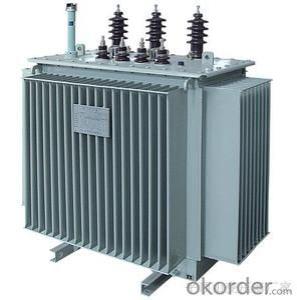
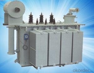
Mining Flameproof Dry-Type Transformer KBSG9
- Ref Price:
-

- Loading Port:
- Shanghai
- Payment Terms:
- TT OR LC
- Min Order Qty:
- -
- Supply Capability:
- 1000sets set/month
OKorder Service Pledge
OKorder Financial Service
You Might Also Like


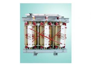
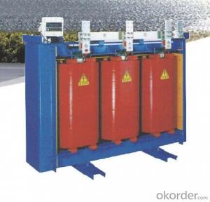
1.Product description
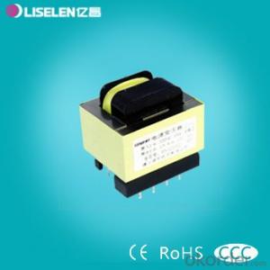
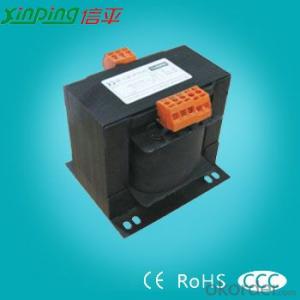
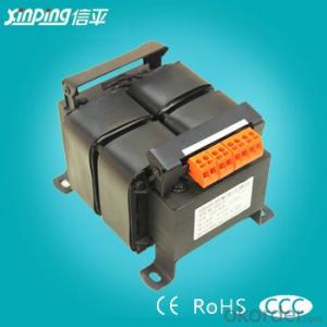
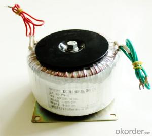
KBSG9 series mining flameproof dry-type transformersuit for not only mines filled with firedamp mixed gas, grime and explosive gas, but also the gas and steam environment that can not erode metal or destroy insulation. the transformer has the merit of high strength, low temperature rise, good cooling and waterproof property, and easy maintenance.
2.Functional characteristics
Functional characteristics
1.The KBSG9-50-1600/10(6) mining flameproof of dry type transformer conforms to GB82862005 the requirement of “mining flame proof movable substations”, its no load, load loss is 10% less than original standard the no-load current short-circuit impedance has diminished too. 2.The insulation material adopt the H level or the C level insulation material, the thermal is good, it is suit for long time operation 3.3 Phases,50Hz,ANAN 4.High strength, low temperature rise, good cooling and waterproof propert, and easy maintenance.
Service conditions
1.The installation is not higher than 1000m(normal)special environment gives explanation in addition
2.Ambient temperature
Highest temperature: 40˚C
Maximum monthly average temperature: 30˚C
Maximum annual temperature: 20˚C
Lowest temperature: -5˚C
3.The surrounding air relative humidity is not greater than 95%(25˚C)
4.In the mine,with methane, dust explosion danger is well
5.No vibration the gradient is less than 15˚C
6.No gas or steam to corrode metal needed or destroy insulation
7.Non-water drop sit
8.Power supply voltage profile approximate to a sine wave
9.The three-phase supply voltage approximate symmetrical
Scope of application
Mine filled with fire damp mixed gas, grime and explosive gas; the gas and steam environment that can not erode metal or destroy insulation
6KV Mining Flameproof Dry-Type Transformer Technical Specification(KBSG9)
| Rated capacity(kVA) | Voltage schedule(kV) | Vector group | Short circuit impedance(%) | Consumption(W) | No-load current(%) | Weight(kg) | Outline dimension(mm±10%) | ||||
| HV | LV | No-load(kw) | Load(kw) | Length | Width | Height | |||||
| KBSG-50/6 | 6 | 0.693/0.4 1.2/0.693 3.45 | Yu0(d11) | 4 | 350 | 550 | 2.5 | 1250 | 2075 | 1100 | 1050 |
| KBSG-80/6 | 450 | 780 | 2.5 | 1300 | 2150 | 1100 | 1100 | ||||
| KBSG-100/6 | 520 | 920 | 2.5 | 1400 | 2150 | 1100 | 1100 | ||||
| KBSG-160/6 | 700 | 1300 | 2.0 | 1500 | 2200 | 1100 | 1220 | ||||
| KBSG-200/6 | 820 | 1550 | 2.0 | 2100 | 2650 | 1100 | 1400 | ||||
| KBSG-250/6 | 950 | 1800 | 2.0 | 2470 | 2690 | 1100 | 1420 | ||||
| KBSG-315/6 | 1100 | 2150 | 1.8 | 2895 | 2830 | 1100 | 1410 | ||||
| KBSG-400/6 | 1300 | 2600 | 1.8 | 3260 | 2920 | 1100 | 1440 | ||||
| KBSG-500/6 | 1500 | 3100 | 1.5 | 3700 | 2990 | 1100 | 1475 | ||||
| KBSG-630/6 | 1800 | 3680 | 1.5 | 4120 | 3050 | 1100 | 1550 | ||||
| KBSG-800/6 | Yu0(d11);Yyn0 | 2050 | 4500 | 1.0 | 5300 | 3100 | 1100 | 1430 | |||
| KBSG-1000/6 | 2350 | 5400 | 1.0 | 5700 | 3160 | 1100 | 1480 | ||||
| KBSG-1250/6 | Yu0;Yyn0 | 2750 | 6500 | 1.0 | 6600 | 3200 | 1100 | 1520 | |||
| KBSG-1600/6 | 3350 | 8000 | 0.8 | 7600 | 3260 | 1100 | 1570 | ||||
| Rated capacity(kVA) | Voltage schedule(kV) | Vector group | Short circuit impedance(%) | Consumption(W) | No-load current(%) | Weight(kg) | Outline dimension(mm±10%) | ||||
| HV | LV | No-load(kw) | Load(kw) | Length | Width | Height | |||||
| KBSG-50/10 | 10 | 0.693/0.4 1.2/0.693 3.45 | Yy0(d11) | 4 | 390 | 680 | 2.5 | 1250 | 2075 | 1100 | 1050 |
| KBSG-80/10 | 490 | 880 | 2.5 | 1300 | 2150 | 1100 | 1100 | ||||
| KBSG-100/10 | 560 | 1050 | 2.5 | 1400 | 2150 | 1100 | 1100 | ||||
| KBSG-160/10 | 800 | 1500 | 2.0 | 1500 | 2200 | 1100 | 1200 | ||||
| KBSG-200/10 | 950 | 1800 | 2.0 | 2200 | 2760 | 1100 | 1480 | ||||
| KBSG-250/10 | 1100 | 2100 | 2.0 | 2760 | 2800 | 1100 | 1510 | ||||
| KBSG-315/10 | 1300 | 2500 | 1.8 | 2990 | 2840 | 1100 | 1500 | ||||
| KBSG-400/10 | 1500 | 3000 | 1.8 | 3430 | 2940 | 1100 | 1550 | ||||
| KBSG-500/10 | 1750 | 3500 | 1.5 | 3800 | 3020 | 1100 | 1600 | ||||
| KBSG-630/10 | 2000 | 4100 | 1.5 | 4380 | 3140 | 1100 | 1410 | ||||
| KBSG-800/10 | Yy0(d11);Yyn0 | 2300 | 5100 | 1.2 | 5400 | 3190 | 1100 | 1490 | |||
| KBSG-1000/10 | 4.5 | 2600 | 6100 | 1.2 | 6500 | 3240 | 1100 | 1530 | |||
| KBSG-1250/10 | Yy0;Yyn0 | 3100 | 7400 | 1.0 | 7100 | 3300 | 1100 | 1580 | |||
| KBSG-1600/10 | 5 | 3800 | 8500 | 1.0 | 8050 | 3350 | 1100 | 1630 | |||
- Q: I am using an audio transformer in a schematic, but I don't understand why. Can someone explain how a 1000 ohm to 8 ohm audio transformer works? (Radio Shack #273-1380)
- The transformer is for impedance matching, but in your circuit could be for some other purpose, e.g. I have one in a DC-DC voltage converter, putting out abt. 75V from a 9V battery. Another, I have as an isolation transformer from a computer soundcard to an external circuit. The impedance match function is usually matching a radio circuit impedance to a loudspeaker impedance (8 ohms). So far as pinouts, look in online catalogue. However, the primary connections are green and blue, with a black centre tap. The 8 ohm speaker secondary winding has red and white wires.
- Q: Transformers of the three transformations are the three?
- Transformer's three transformations are: The transformer can change the voltage. Transformers can change current. Such as current transformers. Transformers can change the impedance. Such as impedance converter. Transformer is the use of electromagnetic induction principle to change the AC voltage of the device, the main components are primary coil, secondary coil and core (core). The main functions are: voltage conversion, current conversion, impedance conversion, isolation, voltage regulator (magnetic saturation transformer) and so on. Transformers can be divided into: power transformers and special transformers (electric furnace variable, rectifier, power frequency test transformers, voltage regulators, mine transformers, audio transformers, intermediate frequency transformers, high frequency transformers, impact transformers, instrument transformers, Transformers, reactors, transformers, etc.). Circuit symbols commonly used as the beginning of the number. Example: T01, T201 and so on.
- Q: I have 13 lights with 12 volts 35 Watts on each light for each tree, the outlet is 120 volts current now. Should I buy 300Watt or 600Watt low volts transformer to supply all lights? Need your advise!
- you need to drop lights down to 25 watts ,and use the 300 , the 600 is just 2 300s not a solid 600. check out malibu lights web site.
- Q: I have a 150 watt bank of photovoltaic cells that run at 12 volts (PWM mode non-mppt charge controller). My question is, by substituting a dc transformer (one that boosts current and steps down to 12v) for a current boosting mppt, can I run the solar panels at their full rating even though they are connected to a 12 volt battery bank? The 12v batteries, when directly connected to the solar panels, drop the output because the panels output their full current at a higher voltage.I am also wanting to apply this logic to a wind turbine that outputs a maximum of 30 volts dc. I am thinking that if the switching transformer works for the solar panels, it would also work to step down the wind turbine's harsh dc voltage to a current boosted 12v state. Would this theoretically work?
- Transformers don't work on DC. You need a DC to DC converter.
- Q: A 8000kva transformer can bring the maximum load
- Transformers are best not to run full of the efficiency of remember the best 60 to 80%
- Q: I Watch Transformers,But Alot Of People Seem To Hate It.
- I don't know because Optimist Prime (think that's how you spell it) rocks.
- Q: What are the specifications of the transformer capacity?
- The choice of transformer capacity has a great impact on the comprehensive investment efficiency. Transformer capacity selected too large, there "big horse car" phenomenon, not only a one-time investment, no-load loss is also large. Transformer capacity selected too small, transformer load loss increases, economically unreasonable, technically not feasible.
- Q: How do I choose a transformer? The
- Select the transformer, you can not choose too large, can not choose too small According to the following method to select the transformer capacity. ???There is a very important data is not provided, is the load at the same time coefficient. Transformer with the actual load and equipment rated power ratio is called the transformer load factor. The concept of the load factor for the load is the probability that the load is used at the same time, also called the coefficient or the simultaneous coefficient, which is the probability of simultaneous use of the device. The total load is 300kw, but they are used at the same time there is a probability that the probability is the load factor. It is impossible to always use at the same time. Of course, you can according to the actual situation to calculate their own, power factor selected 0.80. ??With this formula, s = p * kX / cosφ Transformer capacity s = device rated power p × transformer load rate kx / power factor cosφ = (300 × kX) × 0.80 This is the transformer capacity. ???Do not know what the motor is used under the circumstances, so it can not be calculated, and only calculate the same time after the generation of the formula into the above formula. If the coefficient is 0.9, then the results of about 340 kVA, are used at the same time, that is, 375KVA, consider a certain margin and spare capacity, that can choose 400KVA. In addition to the above considerations, in particular, consider the motor starting current factor, select the transformer more reliable. As far as possible by the big do not rely on small. And the standard capacity of the transformer level 315,400,500,630KVA, 315KVA a little small, 500KVA big and no need. So choose 400kvA it
- Q: From the following transformer, how would I calculate:a) the equivalent impedance on the low-voltage sideb) Converting the impedance found in (a) to it's per-unit quantities
- a) the turns ratio of the transformer is 20 to1 so to refer an HV side impedance to the LV side you divide it by the square of the turns ratio which in this case is 400 which gives: 0.001+j0.00025 ohms. b) There's a certain amount of freedom in doing this for you may define the per-unit impedance base however you want. It is however rather usual to define it as VA / I^2. Here I 5000/2400 2.083 amps So base impedance HV side 5000/2.83? 624 ohms making the given impedance (0.4+j0.1)/624 p.u. This p.u. value should be the same on either side of the transformer. Nice to see you around again but do I notice you haven't improved at saying please when you want someone to do something for you for nothing. If you can't learn that there's not much use in learning all these technical skills. You're going to remain a clumsy oaf!
- Q: I have 12 x 12V 10W lamps in series would I be correct in saying I need a 230-12V 120W transformer to suit?
- 12 12V lamps in series need 144V to operate. Running this light string at a higher voltage will draw more current and burn out your bulbs. It is true that 12 x 12V 10 W lamps will draw 120 W plus the dissipation of the transformer so you never, never want to run a transformer at full strength for any period of time because it will heat up and fail. A good rule of thumb is to size your transformer at twice its load so you will need a 240W transformer with 144V output for this application.
Send your message to us
Mining Flameproof Dry-Type Transformer KBSG9
- Ref Price:
-
- Loading Port:
- Shanghai
- Payment Terms:
- TT OR LC
- Min Order Qty:
- -
- Supply Capability:
- 1000sets set/month
OKorder Service Pledge
OKorder Financial Service
Similar products
Hot products


Hot Searches
Related keywords

