

Packaging & Delivery
| Packaging Details: | seaworthy bare bundles |
|---|---|
| Delivery Detail: | 15 days |


OKorder Service Pledge
OKorder Financial Service
You Might Also Like
Steel Grade:steel
Standard:AISI, GB
Wire Gauge:5.5mm--16mm
Place of Origin:Shandong, China (Mainland)
Type:Other
Application:nut,bolt, screw
Alloy Or Not:Non-alloy
Special Use:Cold Heading Steel
Model Number:ML08,ML35,ML40Cr
Brand Name:Qinggang
| Packaging Details: | seaworthy bare bundles |
|---|---|
| Delivery Detail: | 15 days |
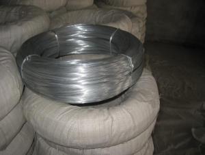
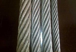
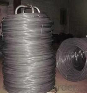
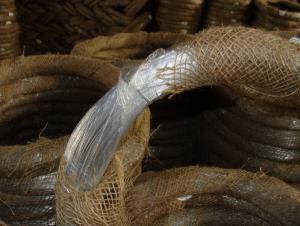
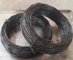
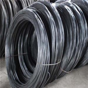
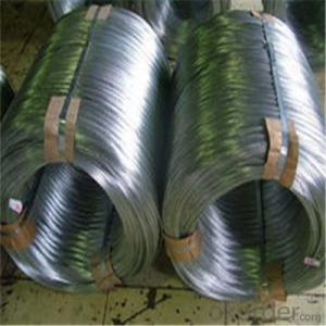
Steel Wire-ML08,ML35,ML40Cr
cold heading steel.As the main raw material needed by the standard pieces manufacture industries, the cold heading steel, standard executed is GB/T64782001, is used to make work pieces in every specification such as bolt, screw, nut etc. Because of the large deformation in the process of cold heading, the steel grade is required to have less content of sulfur and phosphor, less impurity, excellent machining and mechanical performances and accurate rolling tolerances. QIS already could produce the cold heading steel wire coil for cold heading in grade of ML08,ML35 and ML40Cr with diameters range of φ5.5mmφ16mm.
Send your message to us
OKorder Service Pledge
OKorder Financial Service
Similar products
Hot products
Hot Searches