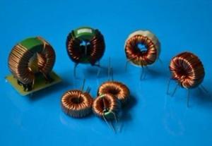
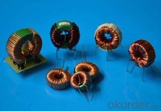
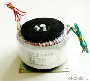
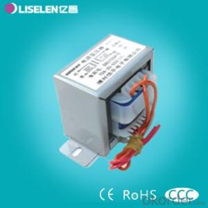
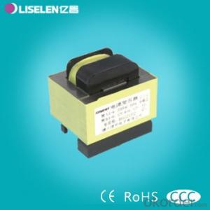
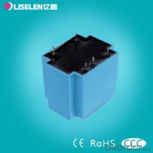
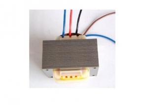
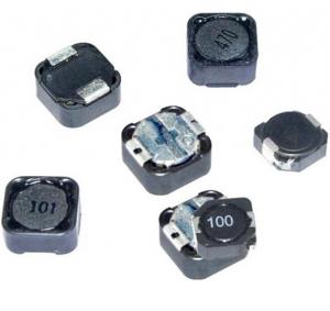
Low Frequency Toroidal Needle Insert PCB Mounted Transformer
- Ref Price:
-

- Loading Port:
- China Main Port
- Payment Terms:
- TT or LC
- Min Order Qty:
- 1000 Pieces pc
- Supply Capability:
- 30000 Pieces per Month pc/month
OKorder Service Pledge
OKorder Financial Service
You Might Also Like
1.Professional engineer
2.Qualified material competative price
3.small loss
4.usage:power phase:single coil
5.structure:toroidal
6.core dimension:adjustable by clients
7.size:follow customer's request
8.Remark:we can produce it according client's requirement
Our products have gained the international certifications, such as CQC, CE, RoHS, UL and so on, from internationally powerful authorities. We have got ISO9001 certificate.We promise to offer the best products to our clients.We look forward to cooperating with all friends for more mutual benefits.
- Q: An LC circuit of a 4-mH inductor and a 200μF capacitor. If the maximum energy stored in the circuit is 10?4 J, what are the maximum charge on the capacitor and the maximum current in the circuit? What are the minimum values?Can someone please explain this in detail. thanks!
- In a RLC circuit w0 a million/sqrt(LC), fw0/(2*pi) (you could convert it from radians to hertz to get 352) w0 is the resonance frequency, it extremely is mutually as the resistance is lowest via making use of certainty the capacitor and inductor cancel one yet yet another out. So at ww0, the resistance is in ordinary terms R IV/R one hundred 55/10 15.5A i'm doubtful at what element you're on your reading, yet convert the two the inductor and capacitor into their impedance type Z. capacitor a million/(jwC), inductor jwL you could desire to apply calculus to discover the minimum of the series resistance (it is w0). and you will study that the impedance of the capacitor and inductor cancel out at this frequency.
- Q: A 33.0 mH inductor has a reactance of 2.00 k.(a) What is the frequency of the ac current that passes through the inductor? Hz(b) What is the capacitance of a capacitor that has the same reactance at this frequency? F(c) The frequency is tripled, so that the reactances of the inductor and capacitor are no longer equal. What is the new reactance of the inductor? k(d) What is the new reactance of the capacitor? k
- The impedance (reactance) for an inductor wL where: w is the angular frequency (i.e. w 2 pi frequency) L is the inductance
- Q: A current of 1.24A in an inductor L results in a stored energy of 0.195J. The current is then changed to 6.47A in the opposite direction. Calculate the change of stored energy.
- Situation 1: MPE1 1/2*L*I1^2 Situation 2: MPE2 1/2*L*I2^2 L doesn't change, since it only depends on geometry and core material properties of the inductor. Solve for L in situation 1: L 2*MPE1/I1^2 Substitute: MPE2 MPE1 * I2^2/I1^2 We are interested in MPE2 - MPE1: MPE2 - MPE1 MPE1*(I2^2/I1^2 - 1) Data: MPE1:0.195 J; I1:1.24 A; I2:6.47 A; Result: MPE2 - MPE1 5.1138 Joules
- Q: An inductor that has an inductance of 24 H and a resistance of 41 ? is connected across a 120 V battery. What is the rate of increase of the current at 0 s. Answer in units of A/s.What is the rate of increase of the current at 0.7 s.Answer in units of A/s.
- Back emf,e L.di/dt where L inductor, di/dt is the rate of change of current. And Z^2 R^2 + XL^2 where Z is impedance, R is the resistance and XL is the inductive reactance. Z^2 41^2 + (2pi*60*24)^2 [Assuming line frequency, f 60 Hz) Z^2 1681 + 8985.6 10666.5 Z 103.27 ohms. Now the total current ,I 120/ Z 120/ 103.27 1.162 amps. Again, T L/R where T Time constant 24/41 .58 sec which is one time constant' In this period, the current flows 63% of the full current 1.162 amp .73 amps. For full current of 1.62 to flow is the time, 5T .58*52.9 sec.And discharge current is 37% 1.162*.37 .59 amps, During this period, back emf occurs Hence the back emf,e .59*sqrt8985.6 or,e .59*94.7 55.8 volts at this voltage, then at .7 sec, di/dt .59/.7 .84 amp/sec at 0 sec, di/dt .84/0 infinity that is like a short circuit current. I think this is the answer. Thank you.
- Q: (a) If an inductor carrying a 1.60 A current stores an energy of 0.250 mJ, what is its inductance?(b) How much energy does the same inductor store if it carries a 2.9 A current?
- W0.5Li^2 whence 2W/i^2 L L 2 *.25 / 1.6^2.
- Q: Before the switch is closed in a circuit consisting of a 4μC capacitor and 0.2 H inductor, the potential across the capacitor is 200 V. At some instant after the switch is closed, the instantaneous current is 0.7 A. What is the energy in the capacitor at this instant?Answer: 31.0 mJPlease show steps. Thank you.
- The total energy before the switch is closed is: 1/2CV^2 2e-6*40000 0.08J 80 mJ At the moment when I 0.7A, the energy in the inductor is 1/2*L*I^2 0.1*0.7^2 0.049J 49 mJ The rest of the energy must be in the capacitor 80-4931mJ Notice that there has to be some resistance in the circuit which would gradually consume the energy. The inductor is modeled as having no resistance but that is ideal.
- Q: A fixed inductance L 1.07 ?H is used in series with a variable capacitor in the tuning section of a radio telephone on a ship. What capacitance tunes the circuit to the signal from a transmitter broadcasting at 6.90 MHz?answer in pFhow to solve this would be great :) a few step by steps maybe Thanks!
- Why 2pi?
- Q: a) oscillatesb) makes x-raysc) is uselessd) shorts out one or bothe) stops all current
- It will oscillate and form a series filter.
- Q: and what are the possible components.
- just basicly, an inductor is a passive electronic component that stores energy as a magnetic field. In it's simplest form an inductor is made up of a coil of wire. The inductance measured in henrys, is proportional to the number of turns of wire, the wire loop diameter and the material or core the wire is wound around.
- Q: An RL circuit consists of two inductors of self-inductance L1 10.00 H and L2 4.00 H connected in parallel to each other, and connected in series to a resistor of 6.00 ? and a battery of 4.00 V (See figure). Assume that the inductors have no mutual inductance. When the battery is suddenly connected what is the inital rate of change of the current in inductor L1?Figure:
- Initially no current flows in L1 or L2, so the voltage drop across R 0 and thus 4 V is applied to L1 and L2. Use the formula V LdI/dt to find dI1/dt and dI2/dt. P.S. You did a bad copy of the imageshack page URL. What you posted actually ends with just as it appears, which is not a URL. That's because you used a simple copy command (ctrl-C or whatever) instead of Copy Shortcut. I'm assuming you have R + (L1 || L2), where + means 'in series with' and || means 'in parallel with'. EDIT: OK, got your URL and it's the way I assumed it was and fits your description.
1. Manufacturer Overview
| Location | Shenzhen, Guangdong, China (Mainland) |
| Year Established | 2006 |
| Annual Output Value | US$2.5 Million - US$5 Million |
| Main Markets | North America; South America; Eastern Europe; Southeast Asia; Africa; Oceania; Mid East; Eastern Asia; Western Europe; Central America; Northern Europe; Southern Europe; South Asia; Domestic Market |
| Company Certifications | CE Certificates |
2. Manufacturer Certificates
| a) Certification Name | |
| Range | |
| Reference | |
| Validity Period |
3. Manufacturer Capability
| a) Trade Capacity | |
| Nearest Port | Shekou,Yantian |
| Export Percentage | 51% - 60% |
| No.of Employees in Trade Department | 3-5 People |
| Language Spoken: | English, Chinese |
| b) Factory Information | |
| Factory Size: | 3,000-5,000 square meters |
| No. of Production Lines | 9 |
| Contract Manufacturing | OEM Service Offered Design Service Offered Buyer Label Offered |
| Product Price Range | Average |
Send your message to us
Low Frequency Toroidal Needle Insert PCB Mounted Transformer
- Ref Price:
-
- Loading Port:
- China Main Port
- Payment Terms:
- TT or LC
- Min Order Qty:
- 1000 Pieces pc
- Supply Capability:
- 30000 Pieces per Month pc/month
OKorder Service Pledge
OKorder Financial Service
Similar products
Hot products

Hot Searches
Related keywords

