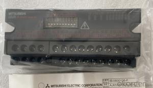


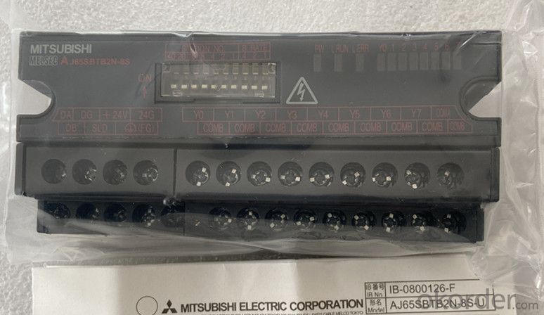

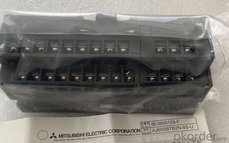

Organic Materials DC Motor Newest Mitsubishi Melsec AJ65SBTB2N-8S
- Ref Price:
-

- Loading Port:
- Shanghai
- Payment Terms:
- TT OR LC
- Min Order Qty:
- 1 kg
- Supply Capability:
- 2000 kg/month
OKorder Service Pledge
OKorder Financial Service
You Might Also Like

Specification
A small remote I / O module used as a remote I / O station for control and
communication links (hereinafter referred to as "CC link"). Its features are as
follows:
(1) The small remote I / O module reduces the volume while maintaining all the
functions of the traditional module.
(2) More models of small remote I / O module series
Waterproof terminals are added to the small remote I / O module series for CC
link system. Along with the traditional terminal block type, there are also
quick connector type modules and FCN connectors
Type and connector type, now there are five models of products.
In addition to the traditional 16 point and 32 point remote I / O modules, an
8-point type is added, so that users can choose the most appropriate module
according to their own purpose and environment.
(3) The 4-wire small remote I / O module is easy to connect to the 4-wire
sensor.
It can be easily connected to the 4-wire sensor through the common pin provided
on each plug. It is not necessary to install relay terminal block.
For 4-wire small remote I / O modules, one sensor is connected to one plug.
Therefore, the sensor can be changed through the plug, reducing the operation
steps.
(4) The terminal block connection makes it easy to connect 2-wire and 3-wire
sensors or loads.
Because the terminal block connection allows the connection of 2-wire and 3-
wire sensors or loads, there is no need for a common connector, which makes the
connection easier.
(5) Minimize wiring
(a) Terminal block module
By using the self tightening screw on the terminal block, the wiring steps can
be significantly reduced.
(b) Quick connector module, connector module
The wiring steps can be significantly reduced by using the parallel wire
pressure wiring method (without welding, stripping the shielding layer and
screwing).
(c) FCN connector type module
Wiring steps can be significantly reduced by using 40 pin connectors for I / O
parts.
(6) Waterproof remote I / O module has improved waterproof and oil proof effect
The waterproof remote I / O module adopts a protective structure compatible
with IP67, which can be used more safely in the presence of water and oil.
(7) Up to 64 remote I / O modules can be connected
In CC link system, each master station can connect up to 64 remote I / O modul
Since each remote I / O module accounts for 32 points, a maximum of 2048 link
points can be set.
(8) The module can be replaced without stopping the CC link system
The dual block terminal block used for CC link cable connection can be used to
replace the module without stopping the operation of CC link system.
(9) It can be installed directly on the machine
The terminal block type remote I / O module can be installed directly on the
machine because there is a live area protected by a finger guard in the area
above the terminal block.
(10) The module can be installed in 6 directions
Small remote I / O modules can be installed in 6 different directions. (there
are no restrictions on the installation direction.)
The module can also be installed with DIN rail.
(11) Transistor output module with improved protection function
Transistor output module in order to achieve better module protection ability,
as a standard model, its design adopts short-circuit protection, overload
protection, overheating protection and overvoltage protection.
Therefore, the reliability of PLC system has been further improved.
- Q: and whyalso does that work when you open circiut a capacitor.
- An ideal inductor appears as a short to DC. Real inductors have some resistance due to the wire they are wound with. Remember the voltage across an inductor V L di/dt if I is constant V 0. An ideal capacitor will appear open to DC. It will charge up to the DC voltage that would appear across it if it were not in the circuit (thevenin voltage). Ic CdV/dt. if V is constant Ic is zero. Electolytic capacitors have some leakage current.
- Q: how do u solve for inductor or L if u have a rlc circuit?
- 1) The reactance of a Capacitor Xc1/(2*Pi*f*C) 2) That of an Inductor is Xl2*Pi*f*L In your case f1.9060 Hz, this is at resonance. First calculate Xc, you have the values of f and C, Pi3.14. Then at resonance XlXc. Now you can calculate L. Note: In these equations, f should be in Hertz, C in Farads and L in Henrys. Convert the units first. You don't need to include the value of R. It only affects the Q of the circuit.
- Q: I have been looking for a type of inductor or coil to pickup the magnetic flux lines from a pair of passing magnets to pass an electrical signal. I am not sure what type to use in this situation. any suggestions?thank you,Michael
- AN OPEN FRAME INDUCTOR WILL BE FINE, BUT THE VOLTAGE PICKED UP WILL BE HIGHER IF INDUTANCE IS HIGHER, AND ALSO IF THE RATE OF CHANGE OF MAGNETIC FIELD IS HIGH. FOR EXAMPLE A SHARP COUPLE OF TEETH PROJECTIING OUT OF SAY A SHAFT COVERING SAY 10 DEG EACH IS MUCH BETTER THAN TWO TEETH SPREAD OVER 120 DEG EACH. AND IF SHAFT SPEED IS HIGHER, THE VOLTAGE PICKED UP WILL BE HIGHER.
- Q: I need help answering this question i have no idea how to do the steps if you could lead me through the steps or tell me what to do that'd be fantastic.An inductor is fabricated with 500 turn of wire, a diameter of 1 centimeter and a length of 2 centimeters, and an air core with a permeability of 1.25X10^-6 H/m. A DC current of 500 mA is made to flow through the inductor.Find:A) The inductanceB) The energy stored in the field:C) The energy stored in the field if a steel core, with apermittivity of 4000 is inserted into the coil.
- A)From physics, you know that: B μNI / h where μ is the permeability h is the height of the loop B is the magnetic flux N number of loops B 0.03125 wb An the inductance L is equal to L B/I L 0.0625 H B) Energy stored 1/2 LI^2 0.007813
- Q: If an AC L-C circuit, which the inductor has internal resistance and given you root mean square voltage of VL, VC, Vrms and Irms of the circuit, and asking you to find the resistance of Inductor which is the internal one, can you find the resistance of inductor through this equation ? Z sqart(R^2 + (XL - XC)^2) ? and we find XL, XC and Impedance of the circuit through given voltage and current and so the resistance of the inductor is R sqart(Z^2 - (XL - XC)^2) is that correct ?
- You know three 4 things (1) V(L) (2) V(C) (3) V(rms) (4) I(rms) You are not given neither omega ( frequency of a.c.) nor values of L and C and so you can not use Z sqrt(R^2 + (XL - XC)^2) since XL 2*pi*f*L and XC (1/2*pi*f*C) and so square this equation , because then we can do something Z sqrt(R^2 + (XL - XC)^2) Z^2 R^2 + (XL - XC)^2 multiply I(rms)^2 both sides. Consider I(rms) I (I*Z)^2 (IR)^2 + (I*(XL) - I(XC))^2 since V(rms) I*Z , V(R) I*R , V(L) I*XL and V(C) I*XC so [V(rms)]^2 [V(R)]^2 + [V(L) - V(C)]^2 you are given V(rms) , V(L) and V(C) so you can find V(R) and after since V(R) I(internal resistance R) you know V(R) and I I(rms) so you can find R. NOTE: If this helps you please remember to vote Best Answer.
- Q: I have a spiral inductor based on the archimedes' spiral. It has a starting radius of 0.0635mm, 0.3175 mm lines and spaces and is 15 turns long. I need to know the straight line length so I can design a rectangular inductor based on the first order length. Any assistance would be greatly appreciated.Thank you.
- Why not just design it based on the square spiral, and the required inductance and Q value?
- Q: a)A capacitor offers infinite resistance to AC and Inductor to DC b)A capacitor offers infinite resistance to DC and Inductor to ACc)A capacitor offers no resistance to DC and Inductor to DCd) A capacitor offers infinite resistance to DC and Inductor offers no resistance to ACpls send me the correct answer and the reason for the answer ?
- B - A cap is a short to AC and an open to DC. While an inductor is a short to DC and an open to AC. The reactance of an inductor is 2*pi*f*l. If frequency is large (AC case) the reactance is also large, like and open. If frequency is 0 (DC case), then the reactance is 0, like a short. For caps, it is just the opposite as reactance 1 / 2*pi*f*C
- Q: Calculate the inductance of an air-core coil with the following specifications: length 20 cm, #of turns 200 and diameter of core 2 cm.Could you show your work if you know how to do it? Thanks :)
- L 0.001 N?r? / (228r + 254l) where L is the inductance in henrys, r is the coil radius in metres, l is the coil length in metres (0.8r) and N is the number of turns. This formula applies at 'low' frequencies. At frequencies high enough for skin effect to occur a correction of up to about -2% is made. Old school version in Imperal measurement is La?n?/(9a+10l) a and l are in inches/
- Q: An inductor has an inductance of 0.075 H. The voltage across this inductor is 64 V and has a frequency of 660 Hz. What is the current in the inductor?
- it is like asking me what type of air am i in a position to devour? the tummy is for nutrition and the lungs are for air. So too, physics are for my human nature and faith is for my soul.
- Q: I need this very badly for my Electronics Project, but unfortunately I still can't find it! What are the defects and testing of Inductors??? Please help! X(
- TESTING INDUCTORS An inductor is a device consisting of one or more windings of wire with or without a magnetic core. Frequent causes of inductor coil failures are shorted turns, open turns, and changes in inductor value. Small power supply transformers are similar in construction to inductors and can be tested with the capacitor-inductor analyzer shown in figure 4-30. Inductors may be tested in the circuit, but the circuit impedance will have some effect on the readings. It is recommended that you remove the inductor or transformer from the circuit before you perform any tests.
Send your message to us
Organic Materials DC Motor Newest Mitsubishi Melsec AJ65SBTB2N-8S
- Ref Price:
-
- Loading Port:
- Shanghai
- Payment Terms:
- TT OR LC
- Min Order Qty:
- 1 kg
- Supply Capability:
- 2000 kg/month
OKorder Service Pledge
OKorder Financial Service
Similar products
Hot products


Hot Searches

