Hot Dipped Galvanized Razor Wire with Factory Price
- Loading Port:
- Tianjin
- Payment Terms:
- TT OR LC
- Min Order Qty:
- 5 m.t.
- Supply Capability:
- 5000 m.t./month
OKorder Service Pledge
OKorder Financial Service
You Might Also Like
Specification
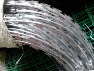
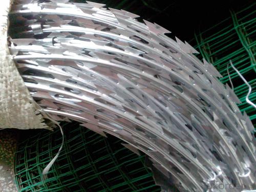
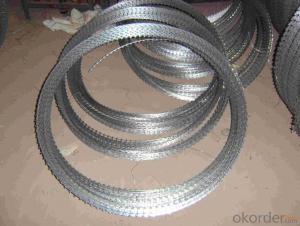
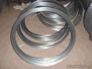
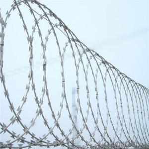
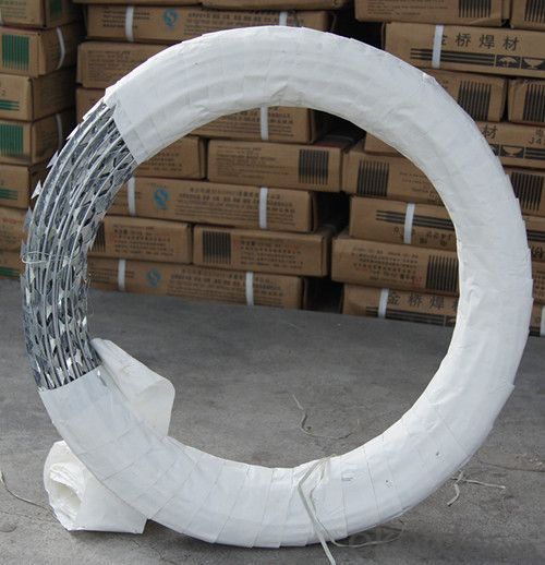
Razor barbed tape is a kind of modern security fencing materials fabricated with razor-sharp steel blade and high-tensile wire. Barbed Tape can be installed to achieve the result of frightening and stopping to the aggressive perimeter intruders, with piecing and cutting razor blades mounted at the top of the wall, also the special designs making climbing and touching extremely difficult.
The wire and strip are galvanized to prevent corrosion. Razor wire can be installed in the form of barbed tape wire or concertina coil to walls or fencings.

Our services:
1. Good after sales service: Any small problem happening will be solved at the most prompt time.
2. We have many years of experience, we have specializing in fastener.
3. Specifications list is available upon your requirement.
4. Packing as your request before shipment.
6. High quality and competitive price.
Usual Specifications:
| Model | Thickness | Wire Diameter | Length | Width | Spacing |
| BTO-10 | 0.5±0.05mm | 2.5±0.1mm | 12±1mm | 13mm | 26mm |
| BTO-12 | 0.5±0.05mm | 2.5±0.1mm | 12±1mm | 15mm | 26mm |
| BTO-18 | 0.5±0.05mm | 2.5±0.1mm | 18±1mm | 15mm | 33mm |
| BTO-22 | 0.5±0.05mm | 2.5±0.1mm | 22±1mm | 15mm | 34mm |
| BTO-28 | 0.5±0.05mm | 2.5±0.1mm | 28±1mm | 15mm | 34mm |
| BTO-30 | 0.5±0.05mm | 2.5±0.1mm | 30±1mm | 18mm | 34mm |
| CBT-60 | 0.6±0.05mm | 2.5±0.1mm | 60±1mm | 32mm | 96mm |
| CBT-65 | 0.6±0.05mm | 2.5±0.1mm | 65±1mm | 21mm | 100mm |
PS: CBT: barbed tape concertina
BTO: barbed tape obstacle
- Q: What does insulated wire do?How does it differ from regular wire used on breadboards?
- Insulated wire is .... insulated. That is, it has a layer of plastic or rubber around it so that there is no exposed metal (except at the ends) and thus minimizes the shock hazard, and also helps prevent accidental shorts between wires. Non insulated wire is bare, it has no insulation, it's just a thin copper bar. You can use either on breadboards, so I don't know what you mean by regular wire. .
- Q: Okay I have a question I have an 8 gauge wire kit and it says 350 watts peak. What the difference when there is the same 8 gauge wire that says 800 watts peak does this really matter? Thanks guys
- wrong wire is not wire. the gauge is the size of wire but the material and insulation determine the wattage it is capapble of carrying. cheap wire carries less current than non-cheap wire does.
- Q: how are lights grounded on a car? Seems like all the wires to the light have electricity running to them.
- a ground runs from light assembly to the body of the car (unit body cars)usually just trace the wires if you can or look up a wiring schematic on the internet for your car that's the best thing to do actually or buy a manual with the electrical diagrams good luck
- Q: does anyone know what wires go on which post on a 1995 chevy lumina 3.1 starter? it was off when i bought the car and im lost. i cant find a straight answer anywhere. a picture of the wiring in question is an instant best answer lol
- it only has on wire and its not a very big wire shouldn't be that hard to find follow the wire off the battery to the solenoid then its one of the wires off of that
- Q: Stereo wire digram
- usually the yellow or orange wire is the memory !
- Q: 2 wires and ground to oven with 3 wires and ground
- You gotta know if the oven is supposed to be a 240 VAC input ... or? and what is the three wires ground a three phase circuit? you had best know for sure before you go connecting anything.
- Q: Is there special speaker wire in order to run 250 watts max rms or will the oem speaker wire in the car be sufficient (did not originally have an amp and is most likely at 50 watts max rms). If I need a special wire for that please let me know what it is called and possibly an example link. Thanks!
- most likely the wire pre ran in the car was 16 guage wire which is fairly small id recomend atleast 12G for speakers and 8G for a power wire.
- Q: If I have wired my 20 amp kitchen receptacles with 12/2 wire which only has a red, black, and ground wire, do I use the red wire for a neutral and the black as a hot?
- that is notably unusual. commonly, the twine used is #12/2 NM-B for abode wiring. yet whilst it is already put in, that is likely to be to no longer basic to alter it now. yet in no way concern the NEC is here! The national electric Code demands the impartial to be white. you are able to purely re-% out the purple conductor with a decrease priced roll of white electric tape. The Code demands the comprehensive conductor on the container to be re-pointed out. Or a sequence of three (3) stripes on the conductor. So use the black on your 'warm', and re-% out the purple with white tape on your impartial.
- Q: Its a 3 wire chandelier, 2 are attached like a regular electric cord and the third is separate. all are the same color. the ceiling has 2 wires. one tan/white and the other is red. I am comfortable with doing the connections but unsure what wires to connect
- One of the chandelier wires will go to the red and the other to the white wire--it does not matter which one goes to which. The third wire is likely bare (or green) and is a ground wire. Connect this wire to the ceiling box and to the third wire in the ceiling if there is one.
- Q: Hello, I couldnt find a more appropriate category for this question, so i'm hoping someone here knows a little about wiring. today my booster fan burnt out, so I had to replace it. I got a 6in-line duct fan from the home depot. When I got home and took it out of the box, there is just wires with no plug on it. I have an old lamp that I took the cord off of, but there is only 2 cords, pos neg. The new fan has 3. white, black, and green. the black is the hot wire, and the green is grounded to the metal of the fan, and the white I am not sure of. I just want to know how to wire this plug to this new fan. if anyone knows how to do this please get back to me. Any help will be greatly appreciated. once again thank you.
- As you say, the black wire is hot and the green wire is ground. The white wire is called neutral. It's the return path for the voltage from the hot wire. Connect the black and white wires to the two power wires in your duct. Hopefully the colors are the same. The hot wire in the duct may be a different color, red or something. Colors like this are frequently used to mean a hot wire that's switched. It sounds like there's a plug for the fan. You can wire on a 3 pin plug and use an adaptor to plug it into a 2 pin outlet or just wire on a 2 bladed plug and leave the green wire off. Make sure it can't touch anything and cause a short.
Send your message to us
Hot Dipped Galvanized Razor Wire with Factory Price
- Loading Port:
- Tianjin
- Payment Terms:
- TT OR LC
- Min Order Qty:
- 5 m.t.
- Supply Capability:
- 5000 m.t./month
OKorder Service Pledge
OKorder Financial Service
Similar products
Hot products
Hot Searches
