


Hot Dipped Galvanized Iron Wire High Quality Factory Price
- Ref Price:
-

- Loading Port:
- Tianjin
- Payment Terms:
- TT OR LC
- Min Order Qty:
- 10 m.t.
- Supply Capability:
- 5000 m.t./month
OKorder Service Pledge
OKorder Financial Service
You Might Also Like


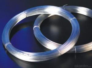
1.Structure of Hot Dipped Galvanized Iron Wire Descrildn:
Hot Dipped Galvanized Iron Wire the Material is super carbon steel, and the Processing is by drawing, hot-dip zinc-plating, the Standard wire gauge from BWG8# to BWG39#
1.Material:
1).low,medium or high carbon steel
2).Thick pure zinc coating firmly adhered to the wire
3).Without zinc flaking off
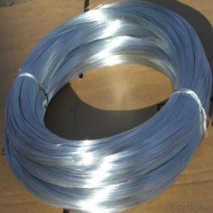
4)Bright finish with even and attractive zinc coating
2.Zinc rate:40g-380g/sqm
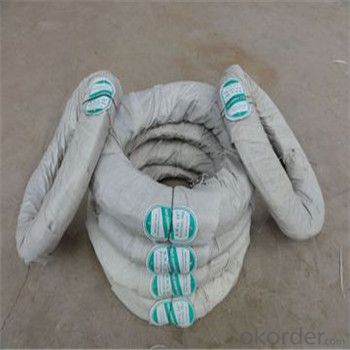
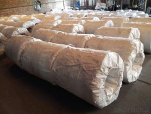
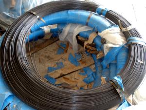
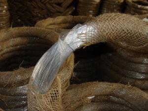
3.Packing:plastic bag inside,then weave bag or hessian bag outside
2.Main Features of Hot Dipped Galvanized Iron Wire:
High corrosion-resisting
Acid resistance
Smooth surface
Longevity
Firm zinc coating
More tensile strength
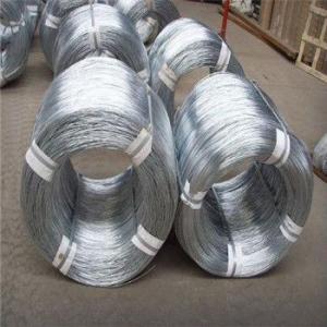
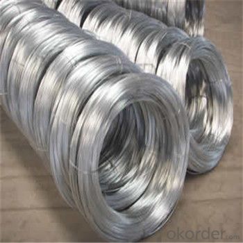
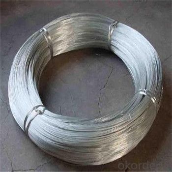
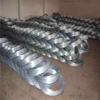
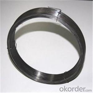
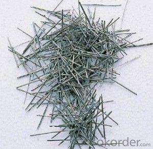
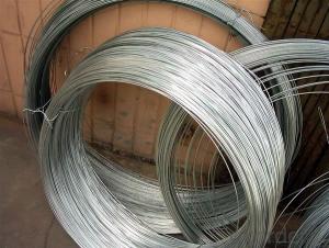
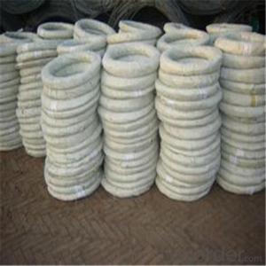
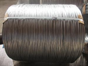
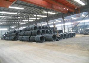
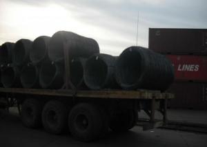
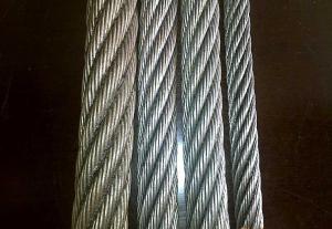
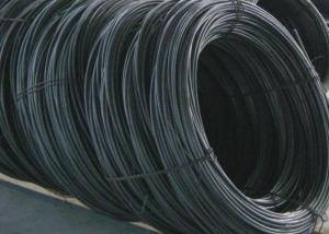
3. Hot Dipped Galvanized Iron Wire Images


4. Hot Dipped Galvanized Iron Wire Specification
Galvanized Wire | |||
Wire Gauge | SWG(mm) | BWG(mm) | Metric(mm) |
8 | 4.05 | 4.19 | 4.00 |
9 | 3.66 | 3.76 | 4.00 |
10 | 3.25 | 3.40 | 3.50 |
11 | 2.95 | 3.05 | 3.00 |
12 | 2.64 | 2.77 | 2.80 |
13 | 2.34 | 2.41 | 2.50 |
14 | 2.03 | 2.11 | 2.50 |
15 | 1.83 | 1.83 | 1.80 |
16 | 1.63 | 1.65 | 1.65 |
17 | 1.42 | 1.47 | 1.40 |
18 | 1.22 | 1.25 | 1.20 |
19 | 1.02 | 1.07 | 1.00 |
20 | 0.91 | 0.84 | 0.90 |
21 | 0.81 | 0.81 | 0.80 |
22 | 0.71 | 0.71 | 0.70 |
5.FAQ
Q:How do you ship the finished Hot Dipped Galvanized Iron Wire?
A:Usually by sea.
Q:Are you a manufacturer?
A: Yes,we have specialized in this field for more than 7 years experience.
Q:What information should I provide,if I want a lowest quotation?
A:The specification of galvanized iron wire .such as material, quantity, wire gauge and coating thickness .
Q:How many days will the samples be finished?And how about the mass production?
A:Generally,3-5 days for samples of galvanized iron wire making, the time of mass production depends on the quantity,18-20 days for 3 5 containers. please noticed that we can offer you free sample to check the quality.
- Q: I have a buffalo tools 2000 watt generator i have been rebuilding. I have searched for a wiring diagram to help but no luck at all my question is about the wires that come out of the section that generates electricity. Outside of all the resets and switches coming right out of the back of the section that creates electricity has 6 wires coming out. Four are hooked to two different plugs two in each plug one set is red the other blue and the last two wires are separate black wires i would think are negative/ground wires i am looking to know what the red wires and blue wires actually are dc/ac volt i imagine just would like to know for sure don't want to blow anything up and help even guesses will be greatly appreciated.
- Only one way to know for sure, Run down to Harbor Freight Tools and purchase a 7 Function Digital Multimeter for $3.00 and test the wires for voltage and if they are grounds or leads.
- Q: i know nothing about wire. thanks. :|
- Solder wire has a lower melting point, allowing you to melt it onto something else. In it's wire form, it will also snap very easily. (not good for fastening things together). Mechanical wire (I'm assuming electrical wire), is designed to withstand high temperatures (and hence, electrical currents), and are usually be bent much more. It's also usually sheilded in rubber (e.g. electrical cords, computer cables, coxial (tv) cable, etc).
- Q: what gauge wires should i use for my 12'' alpine typr r SWR-1242D?
- For the speaker wire going from the amp to the speaker? Try to stay above 16 gauge, I use 12 gauge as over-kill. It costs like 12 cents more per foot and is completely worth it. For the power wire going from the battery to the amp? Use no thinner than 4 gauge power and ground wire assuming your only pushing a single Type-R. Good Luck!
- Q: I made a kill switch for my car. All I need to do now is cut the wire that goes into my engine control module and join it with the switch I made. Would it be fine if I just use wire nuts or some sort of tape to join the wires instead of soldering? The instructions say quot;Step 6: Attach the killswitch wires one to each side of the wire you just cut. Step 7: Tape up all new connection.quot;It says to tape the new connections, but should I use exactly?
- Twisted wires can separate with the daily rattle and bumps of a car. I would crimp or solder it along with a shrink tube to secure it.
- Q: How could you relate greater wire length resulting in greater resistivity to the context of home
- Greater wire length will certainly give you a higher resistance. Since heat is measured in watts, and watts (W) =I^2R, where I=Current and R= resistance, then if you double the resistance of a wire (by making it twice as long) you also double the ammount of watts lost in the wire. Since watts equates to heat, this ammount of heat will make the wire hotter. If you use an extension lead, and wind it round a drum, it can get very hot indeed.
- Q: I bought a new ceiling light and wired it myself. But I cheated by just copying the wiring from the old bracket into the new one. I want to do the other ceiling lights in my home. Supplied with the lights I am using is a 3 - way bracket (sori if terminology is wrong). Anyway the old bracket I copied was 4 way. My lights are wired from the mains supply with 3 live wires, 3 neutrals, and 3 positives. The light unit only has one live/neutral/positive wire. What do I do with the extra mains supply wires? I hope I have made myself clear as I even I am confused. Many thanks.
- Sounds like you have extra wires that are feeding other outlets or lights.
- Q: I have a ceiling fixture outlet which has 4 wires coming out (red, black, white and uninsulated ground). There is only one light switch that controls it. I wanted to attach a light fixture to connect to that, but the light fixture only has 3 wires (red, white and green - ground). How do I connect this light fixture to the 4 wires?
- Canada and the USA Usually the Red wire in the cieling outlet is controlled by the switch. The Black wire in the cieling outlet should be live all the time. Cap the black wire off with the proper size wire nut. The white wire in the cieling outlet is the common wire. The bare wire in the cieling outlet is the ground wire. it should be attached directly to the metal ground screw in the outlet. The green wire on the light fixture must be connected to the ground screw in the cieling outlet. Connect the white wire on the light fixture to the white wire in the cieling outlet Connect the red wire on the light fixture to the red wire in the cieling outlet. If this does not work, whoever did the wiring did not follow convention. Interchange the red and black cieling outlet wires: Connect the red wire on the light fixture to the black wire in the cieling outlet. Cap off the red wire in the cieling outlet with the proper sized wire nut.
- Q: Why when you loop a straight wire into loops (coil), it acquires a higher inductance?
- Imagine two closely spaced parallel wires. If you run a current through one, it creates a magnetic field that induces current into the second wire, which causes an even stronger magnetic field. Now if you run the same current through both wires, they both create magnetic fields that affect each other. Any two loops in the wire are just like two parallel wires with the same current, both creating magnetic fields that affect each other. So a loop is like a bunch of parallel wires affecting each other.
- Q: my questions is what wires go where. i just bought a Hunter thermostat model # 44155c. on my old thermostat the wires are as followes:W2-jumps to quot;F(Yellow Wire)F-Yellow WireO/B-Light Green WireR-Red WireG-Dark GreenC-Red Wire Y-Yellow WireMy new thermostat has these options:RH, RC, G, Y/O, W/B, Y1can anyone tell me what wires go where?thank you
- Well, unfortunately, this particular Hunter model isn't well-designed for operating heat pumps, which is what I'm assuming you've got, since you've got a W2 (aux heat) wire and and O/B (compressor reversal) wire. Still, you can sorta get it to work, but it might take some trial and error, when it comes to the O/B wire, as I'll explain in a minute. Here's the connections you should make: RH - 24VAC hot - connect to R wire RC - 24VAC cool - Jumper this to the RH connector G - Fan - connect to G wire Y - Compressor - connect to Y1 The O/B wire should connect to EITHER the Y/O or W/B, depending on your heat pump. If the reversing valve of the pump is supposed to operate when it heating mode, then you connect to the W/B terminal. If the reversing valve operates in cooling mode, you connect to the Y/O terminal. The other wires should be taped off with electrical tape and left disconnected. These wires are: W2 - auxiliary heat control - leave disconnected (your thermostat can't activate auxiliary heat) F - not sure what this is, to be honest; it might be for controlling a thermostat system check LED C - 24VAC common. Your thermostat doesn't need it.
- Q: electroluminescent wire picture?
- What about it?
Send your message to us
Hot Dipped Galvanized Iron Wire High Quality Factory Price
- Ref Price:
-
- Loading Port:
- Tianjin
- Payment Terms:
- TT OR LC
- Min Order Qty:
- 10 m.t.
- Supply Capability:
- 5000 m.t./month
OKorder Service Pledge
OKorder Financial Service
Similar products
Hot products
Hot Searches

