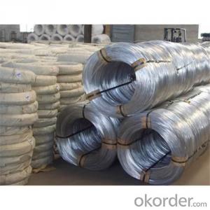

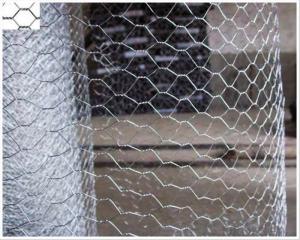
Hot Dipped Galvanized Iron Wire For Hexagonal Wire Mesh
- Ref Price:
-

- Loading Port:
- China Main Port
- Payment Terms:
- TT OR LC
- Min Order Qty:
- -
- Supply Capability:
- -
OKorder Service Pledge
OKorder Financial Service
You Might Also Like


Packaging & Delivery
| Packaging Detail: | 1. Inside with plastic film, outside weaving bag. 2. Inside with plastic film, outside hessian cloth. |
| Delivery Detail: | 15~30 days |
Specifications
1. Material is Q195(C is 0.06% ~ 0.12%)
2. Zinc coating is 40/m2 ~ 60g/m2
3. Tensile strength is 400N ~ 600N
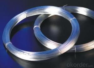
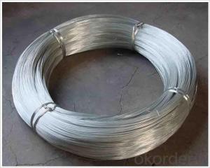
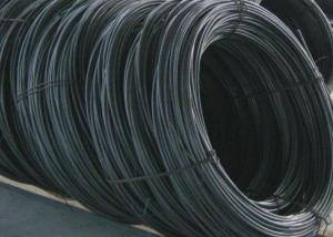
Hot-Dip Zinc-Plating Iron Wire
Material: super carbon steel Processing by drawing, hot-dip zinc-plating Standard wire gauge from 8# to 24# Thick zinc-coating layer Super in corrosion resistance Firm coating layer Custom size available
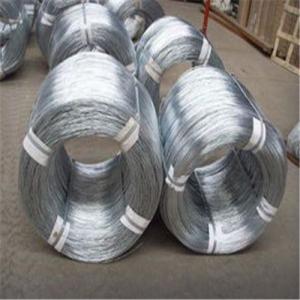
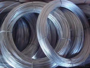
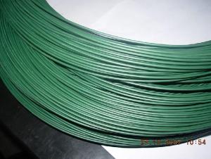
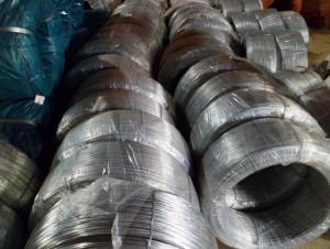
Hot dipped galvanized wire and Electro galvanized wire | |
Metric system | British System |
4.0mm-0.30mm | BWG8-BWG30 |
Tensile strength: 30-55kg/mm2 | |
Zinc coating: 20-32g/m2 6-295g/m2 | |
Packing: inside polyethylene film, outside PVC film or hessian cloth | |
- Q: i am putting in a ceiling fan. there is a black wire and a white wire along with a copper looking wire in the wall. on the fan there is a blue,white,and green. where do i connect this to the wires in the wall? running from a wall switch btw
- connect the fan black wire and the fan blue wire to the house black wire. then connect the white fan wire to the white house wire. connect the short green wire from the fan and fan bracket to the copper wire. the blue is the power wire to the light on the fan. Good luck...
- Q: ive heard multiple people talk about a 'final wire'. what is it exactly? Is it the thickest wire possible? Or is it when you havent gotten your wire changed in a while?
- my othedontist said something about a final wire saying it was steal and is not as flexible the other wires he said in my next appointment i get them im excited that im almost done to because i had my braces as its about to be 6yrs
- Q: I have a '78 jeep cj7 with points type ignition, I was wanting someone to explain exactly how to wire up the coil, starting with the 3 wires from the ignition switch.
- HI use a test light.. hook it up to ground and turn the ignition on. one wire should be hot that goes to the + of the coil. then have someone turn the switch to start (I'd disconnect the wire from the solenoid to the starter so it don't turn ) the test the other two wires one of them should be hot now. that also go the the + of the coil. The last wire well go to the - side of the coil.. You may ask why to hot wires to the coil... one only supplies like 5 to 9 volts to the coil which is all that is needed to run the motor. The other supplies a full 12 volts which is needed for start up only. good luck Tim
- Q: well i've been asking for quite sometime on the correct wiring of a bathroom fan up to the same circuit as my light in the bathroom but i believe i've figured out. but i have a question now about the wire guage.the wire guage in the house is the standard solid 12 or 14 i think(house built in 50's) and the the wire that came with the bathroom fan looks a little smaller or about same size but it's braided .it should be fine to splice the two right?
- Yes, you can. Use insulated wire nuts. I always wrap the wire nut and connection with electrical tape. Safety First! Also my parents have house that was built in 1908 and they didn't use a ground back then. Make sure your house has one.
- Q: The resistivity of a 18.0 m long wire is 3.76E-8 Ω.m and its cross sectional area is 6.52E-6 m2. If the wire carries a current of 1.44 A, what is the voltage across the wire?
- R = ( rho x l)/A Where: R is the resistance, rho the resistivity, l the length and A the area Resiatance of wire = (3.76 x 10^-8 x 18)/6.52 x 10^-6 R = 0.1038 Ohms Voltage across wire = current through wire x resistance of wire V = I x R V = 1.44 x 0.1038 V = 0.14947 V = 0.15 Volts
- Q: While updating the parents basement we needed to replace a very very old 3 way switch. However, the wiring to the Fluorescents seems extreme to me. Here is how i can describle the layout. Panel - junction box - double splice (one to light fixture and one to threeway switch below it)-. From that threeway switch 12-3 wiring to upstairs landing with other threeway switch resides. How should I make my connections to switches? If the other swtiches were not so old I would just copy them.
- A hot wire from the panel to the first three way switch on the common screw. Two runner wires between the two switches on the other two screws. A wire from the common screw on the second switch to the hot wire on the light fixtures. A neutral wire to the light fixtures from the panel. Look at Bert's pictures.
- Q: I have some salvaged wire from a computer power supply and would like to know it's break-down voltage rating. Most hookup wire is rated at 600 volts but unfortunately, all computer stuff is now made in China. The repair job of a vintage piece of equipment requires wire that can withstand 300 VAC.
- Computer power supply cables do not deliver anything like 300 volts, so I would say no, don't risk it.
- Q: I recently took out my old ceiling fan, and now there is a Black, Red, And White Wire hanging from the ceiling, I bought a track light that has a box with a Green, White, and Black wire in it. Which wires am i supposed to connect,It's for the light Switch, and I'm not sure when the house was built, its a Reading, PA Row house.
- This is really simple... The RED is the HOT WIRE for one of the two switches The BLACK wire is a hot Wire for the other of the two switches. The WHITE is the RETURN for both and of course the BARE COPPER WIRE is the ground. So... terminate the red.. Connect black to black, white to white and copper to copper. The switch that controlled the BLACK circuit will now run the track lights.
- Q: The house was built in the 50's. Two wires are coming up from the switch and two wires are coming down from the top of the wall. I do not see a third wire. I attached the wall light wires left wires to left wires and right wires to right wires and light stayed on, when I moved the switch it threw the breaker. So I used may combination and the switch would not make the light work. It appears one wire may be white and one black. Help please!
- The wire coming down from the wall is probably the power line. The wire going to the switch is meant to switch the hot lead lead only. Check the wires on the switch. There is probably a black and white on the switch. You will want to hook the white wire coming from above to the white wire on the light. Hook the black wire coming from above to the black wire going to the switch. Hook the white wire coming from the switch to the black wire on the light. While you are at it take black electrical tape and tape both ends of the white wire that runs to the switch. This will indicate that it is a hot lead.
- Q: But when I look closely (you can't see it in the picture unfortunately) there are some tiny wisps of the coiled copper wire that looks as if it could have been connected to the pulled wire. I'm not sure.How do I connect the wires to make the headsets work again?If you guys need more pictures, please tell me.Thanks in advance!
- don't be afraid to cut the wires, those wires are no good, strip out a fresh strand of wire, just make sure you remember the color coding of the contacts before you cut the wires, be warned though, working with earphone wires can be tricky, the solder is very hard to bind on the tips of the wires and the fibers are a pain, if you know how to solder then that's fine, but if you don't ask help from someone who can
Send your message to us
Hot Dipped Galvanized Iron Wire For Hexagonal Wire Mesh
- Ref Price:
-
- Loading Port:
- China Main Port
- Payment Terms:
- TT OR LC
- Min Order Qty:
- -
- Supply Capability:
- -
OKorder Service Pledge
OKorder Financial Service
Similar products

Hot products
Hot Searches
Related keywords

