


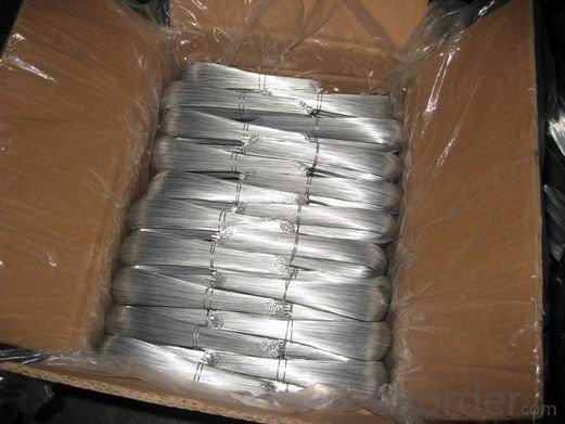
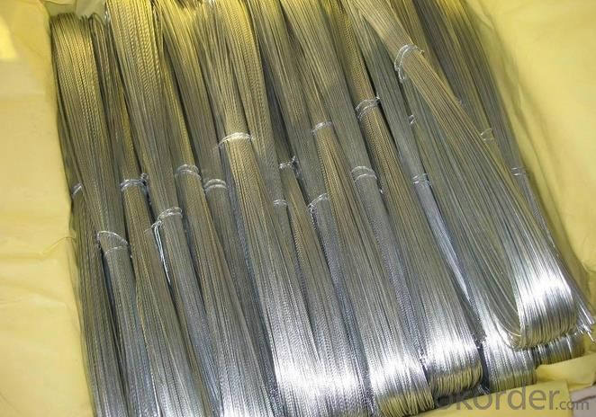
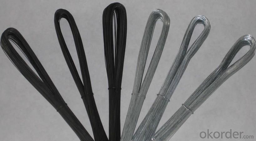
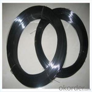
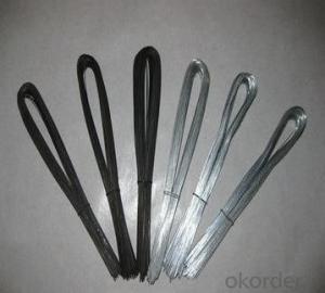
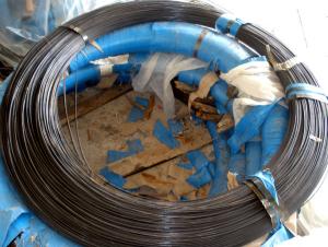
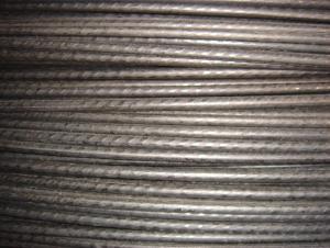
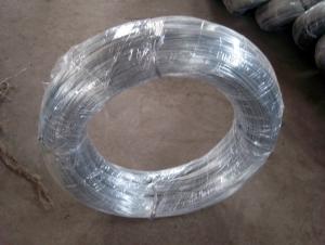
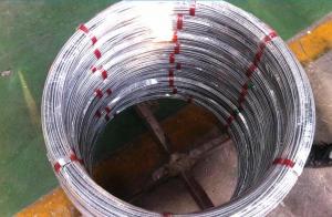
Galvanized U Type Wire
- Ref Price:
-

- Loading Port:
- China Main Port
- Payment Terms:
- TT OR LC
- Min Order Qty:
- -
- Supply Capability:
- -
OKorder Service Pledge
Quality Product, Order Online Tracking, Timely Delivery
OKorder Financial Service
Credit Rating, Credit Services, Credit Purchasing
You Might Also Like


Quick Details
| Place of Origin: | Technique: | Model Number: | |||
| Surface Treatment: | Galvanized Technique: | Type: | |||
| Function: | Wire Gauge: | Feature: | |||
| Color: | Zinc coating: | Galvanized: | |||
| Certification: |
Packaging & Delivery
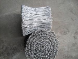
| Packaging Detail: | u type iron wire packing details 1.plastic inside and weaving bag outside 2.plastic inside and hessian outside 3.on request |
| Delivery Detail: | within 10 days after receive your payment |
Specifications
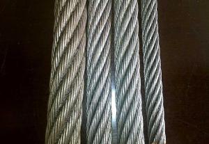
u type iron wire
1.surface:galvanized or PVC
2.Wire diameter: 0.5mm-4.5mm
3.Wire length: 25cm-65cm
4.Sizes can be custom
- Q: I've had my subs wired up for a while but want to see if there is a more efficient way to do it. Hardware: Sony Xplod 800w amp bridgeable amp - What's the best way to wire these up to get the most volume?
- wire the voice coils to series on each sub and then wire the subs in parallel to the amp and voila.
- Q: I have just bought a Clarion CZ500 and am trying to run a remote wire to the amp. Where do i connect the wire to the head unit? Please Help
- Well newer head units have a blue with a white stripe but older are solid blue so if u got blue with stripe it goes there if not solid blue
- Q: im confused which wires are what, theres two wires...no colors?
- I need to know is the wires silver brass colors the silver should be the hot wire .If you live in the states call me at mike'sdiy 301-784-6227 ill walk you through it step by step.
- Q: Kind of a confusing question I guess. I want to cut a wire that contains 3 other wires and splice into them then reconnect them. is all I need relatively the same gauge wire or is it potentially different type like some sort of special speaker wire..? Should be one positive one negative and the other some sort of signal for sound. (Microphone to a speaker). All I need is standard copper wire?
- Hello Rocky: You need to be more specific. What are you attempting to do? I know you want to splice a three-ply wire, but what is your end purpose?
- Q: My computer kept switching all the time when ever I was playing a game. So I had alook in my computer and a wire I bought to extend the CPU wire. The extended wire had burnt so bad that the wire was showing out of the insulting. Will this effect my computer in any way because it was working fine and I shut it down before I took the wire out does it matter that my psu only has a 4 pin for CPU and my motherboard has a 8pin?
- Buy a replacement cable. This has probably happened because one of the connectors is loose which would cause it to get hot because it has a lot of power flowing through it. Hopefully it hasn't damaged the pins on the motherboard with the heat, I've seen motherboards wrecked that way.
- Q: I have a ceiling fixture outlet which has 4 wires coming out (red, black, white and uninsulated ground). There is only one light switch that controls it. I wanted to attach a light fixture to connect to that, but the light fixture only has 3 wires (red, white and green - ground). How do I connect this light fixture to the 4 wires?
- U.S. house? Recent (last 50 years) construction? Not knowing how the box was wired originally presents a problem, but only a small one. Green wire ground to uninsulated ground. White wire to white wire (neutral). You'll have to guess whether to use the red or the black wire from the box to connect to the black wire from the fixture. So, take a guess, and cap the other one with a wire nut. If you're wrong, try it the other way. Just be sure to turn the circuit breaker off before wiring, or re-wiring. Or, while the power is off, inspect how the switchbox is wired. Maybe you'll see that the red wire is capped in the switchbox; suggesting that you should use the black wire. Or (more likely) the red wire is switched, and the black wire is always hot. (This would be useful if the box were pre-installed for a ceiling fan.)
- Q: what is the best speaker wire for some subwoofers that are rated between 500rms watts to 750rms watts
- loxotox has finally conviced me that he is obviously lying about his accomplishments. There is no way in hell that 2 or 4 gauge wire will fit to wire up the coils on these subs. It is physically impossible, unless you shave down the wire. I would not recomend doing that at all, that is speaking from what I know about electronics. I would suggest using 12 or maybe 10 gauge wire. You can use lighter wire but will not get optimum performance from your sub.
- Q: Ok, bought this mower at an estate auction for next to nothing. It looks like its never been used. Previous owner ripped out all the wires to the ignition switch so it wouldn't sell I guess. It's the craftsman lt 1500. Model number 247.288812. It has the 17.5hp bs motor in it. Does anyone know the correct way the wires go to the switch? There are 3 red wires so its a bit unlike what im used to. Thanks in advance!
- On my sears mower with an electric clutch the switch is wired like this. G terminal is a black wire to ground. B terminal is a red wire to the ammeter. S terminal is a white wire to a safety switch. M terminal has two black wires one to the ignition coil and the other to a safety switch. L teminal is a red wire to the alternator and a red wire to the PTO switch.
- Q: Domestic wiring from bank to bank.
- I wire money all the time at my job. It takes a little while for the bank to process everything, but it is generally less than 2 hours.
- Q: i have a 00 gmc yukon and tried installing my cd deck. i pulled off the original harness from the stock deck radio and now its just all wires (its my first so i didnt know), i connect the alpine deck wires and tried to connect them all together. i had a few figure out, except a small noise coming from my stock tweeters every time i step on the pedal. then my speed odometer sensor was going with the bass of my subs... whats wrong? can someone find me a chart of what color wires supposed to go where? thanks for your help
- do now no longer combine the speaker outputs out of your head unit. you could harm the final unit this type. you at the instant are no longer harming something via using working a a hundred-watt speaker on a lots cut back powered amplifier (and you will now no longer inevitably boost the sound intense high quality via using switching to a speaker with a cut back skill score). The a hundred-watt score is only the optimal skill it truly is stated for this speaker; it does now no longer propose that it demands that lots skill. in case you pick for extra advantageous skill than your CD deck substances, you will might prefer to function an outdoors amplifier.
Send your message to us
Galvanized U Type Wire
- Ref Price:
-
- Loading Port:
- China Main Port
- Payment Terms:
- TT OR LC
- Min Order Qty:
- -
- Supply Capability:
- -
OKorder Service Pledge
Quality Product, Order Online Tracking, Timely Delivery
OKorder Financial Service
Credit Rating, Credit Services, Credit Purchasing
Similar products


Hot products

Hot Searches

