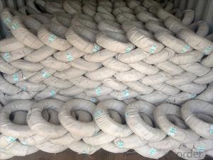
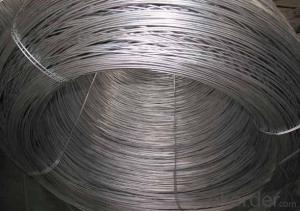
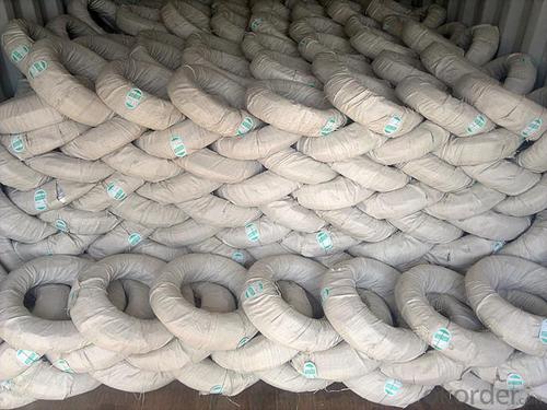
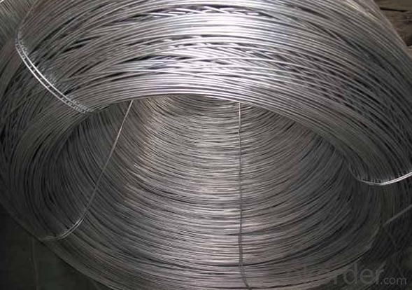
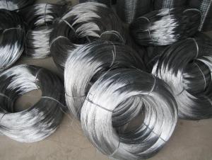
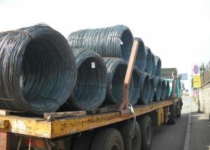
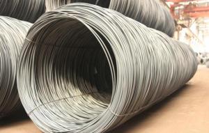
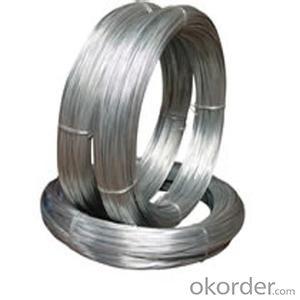
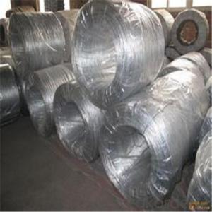
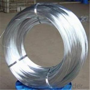
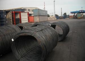
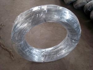
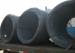
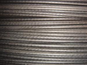
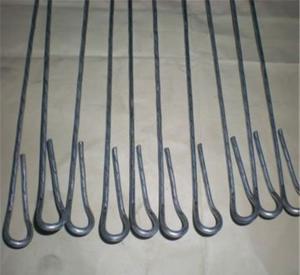
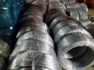
Electro Galvanized Wire
- Loading Port:
- China Main Port
- Payment Terms:
- TT OR LC
- Min Order Qty:
- -
- Supply Capability:
- -
OKorder Service Pledge
Quality Product, Order Online Tracking, Timely Delivery
OKorder Financial Service
Credit Rating, Credit Services, Credit Purchasing
You Might Also Like
Quick Details
| Place of Origin: | Wire Gauge: | Model Number: | |||
| Surface Treatment: | Galvanized Technique: | Type: | |||
| Function: |
Packaging & Delivery
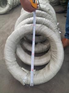
| Packaging Detail: | 25-50kg/coil, wrapped with PVC inside and weaving bag outside |
| Delivery Detail: | 20 DAYS |
Specifications
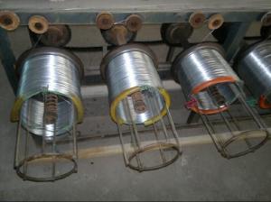
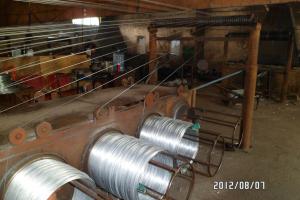
electro galvanized wire(factory)
1.Certificate: ISO9001
2.diameter: 0.14mm -5mm
3.tesile strength:340-1300mpa
4.Sample:
1) Hot-dipped Galvanized Wire
2) Electro Galvanized Wire
The wire diameter range: 0.14-5.0mm.
Wire Gauge | SWG in mm | BWG in mm | In Metric System mm |
8# | 4.06 | 4.19 | 4.00 |
9# | 3.66 | 3.76 | - |
10# | 3.25 | 3.40 | 3.50 |
11# | 2.95 | 3.05 | 3.00 |
12# | 2.64 | 2.77 | 2.80 |
13# | 2.34 | 2.41 | 2.50 |
14# | 2.03 | 2.11 | - |
15# | 1.83 | 1.83 | 1.80 |
16# | 1.63 | 1.65 | 1.65 |
17# | 1.42 | 1.47 | 1.40 |
18# | 1.22 | 1.25 | 1.20 |
19# | 1.02 | 1.07 | 1.00 |
20# | 0.91 | 0.89 | 0.90 |
21# | 0.81 | 0.813 | 0.80 |
22# | 0.71 | 0.711 | 0.70 |
- Q: has black wires.
- Two black wires in the box would be a hot from the supply and a switched hot to the load. If the timer has only two wires then it should be pretty easy to just connect them. If they are marked line and load then you would have to hook the wire for line to the wire in the box that is always hot from the supply and the other to the wire marked load. If you are still unsure then it really is not a job for you alone, enlist the help of someone with a bit more experience or even an electrician.
- Q: ok so the passenger side back floorboard was getting wet and i believe the water to have corroded the wiring to my radio i've taken care of the water problem and know how to reconfigure the wiring but do i need to be worried about the security system while tinkering with the wiring see as how sensitive the security in these cars are i figured id check and see what you guys have to say about this pls also give resources as to how you know
- If you are going to replace wire by wire , you can do that first unplug the battery and be very care full with orange and pink wires, try to solder the new wires the factory amplifier is in the trunk left side good luck new wiring is $700 from the dealer and the only place to buy it new good luck
- Q: I am wiring a cd player in my truck is it necessary to get a wire harness that is made for the year make and model of my truck or can I just cut the factory terminals off and just connect the like colors?
- While a wiring harness isn't strictly necessary, It's highly recommended. The wiring color code on an aftermarket head unit will match up properly with a vehicle-specific wiring harness. The wire colors of your vehicle wiring will NOT be the same as the wire colors on your aftermarket unit. You have to match the wires up according to function, not according to color.
- Q: i need to know how to rewire it to make it fire the only wire that is still there is the one that runs to the distributor cap all the other wires are gone is it sopose to wire to the key please help
- to the + terminal of the coil, run a wire that sends 12v. when the ignition switch is turned on.
- Q: have black (hot) and 2 whites from the house. Got Black,green.blue.and white from the fan. Any clues on how to wire this? There is a light switch involved. I know to match the colors but what do with the blue (light) wire is beyond me.
- Mark is Correct except for one thing that caught my attention: you said you have 2 White Wires and 1 Black Wire coming from the house.....WHY 2 White Wires and only 1 Black, Doesn't add up Correctly, unless one of those White Wires was marked with a piece of Black Tape to identify it as a second Hot Wire which would then be used to separate the Fan Motor from the Fan Light by each having its own separate power source.......Be Careful!!
- Q: hey im wiring up a headunit to my L300 van. The factory headunit wasnt there and im having trouble connecting which colour wires to the factory colour wires. if anyone knows which coulours go to what would be much appreciatedcheers.
- Hi does anyone knows where the stereo looms connect back to .i.e. fused?
- Q: Kind of a confusing question I guess. I want to cut a wire that contains 3 other wires and splice into them then reconnect them. is all I need relatively the same gauge wire or is it potentially different type like some sort of special speaker wire..? Should be one positive one negative and the other some sort of signal for sound. (Microphone to a speaker). All I need is standard copper wire?
- Wires are as different from each other as people with almost as many variations. Wires are designed for specific purposes. For audio, the different color wires are used for phasing of the speakers. You won't get anything out of a speaker by connecting a microphone to it unless there is an amplifier between the two components. Generally, I mean really generally, if you keep the same gauge wires and connect the same wire colors together, you should be okay. But that greatly depends upon what you are really doing with the wires.
- Q: I am building an ice chest boombox and want to wire a toggle (on/off) switch to turn the amp on and off....the amp is wired directly to the battery....my question is that I am using 6 gauge wire....but can't find any female spade connectors that are 6 or even 4 gauge to hook to the terminals on the switch.....what is a simple way to do this....am I going to have to solder the wire straight to the terminals?
- Why not wire the toggle switch into the remote + wire? The one that turns the amp on and off with the head unit. 7/5/2013**** Leave the power supply wire alone. The thick 4 gauge wire that runs from the battery directly to the amp, leave it alone, don't put a toggle switch inline on that wire. Instead there's a wire from your head unit (or ignition) that runs to your amp, it turns on the amp when the head unit turns on or your ignition key is in the on position. It's usually 16 or 14 gauge. That's the wire where the toggle switch belongs. Look at your amp, this wire I am speaking of is probably labeled remote+ or ign or something like that and it's usually located next to your power and ground connections on the amp.
- Q: what to do if i unhooked my starter without unhooking my battery and the hot and gound wire caught on fire
- Be thankful that's all that happened. You could loose fingers doing the starter motor without disconnecting the power to it. Among many, many, other things.... Follow the advice posted from othes here..
- Q: can someone tell me what wire arcing is?
- Arcing Definition
Send your message to us
Electro Galvanized Wire
- Loading Port:
- China Main Port
- Payment Terms:
- TT OR LC
- Min Order Qty:
- -
- Supply Capability:
- -
OKorder Service Pledge
Quality Product, Order Online Tracking, Timely Delivery
OKorder Financial Service
Credit Rating, Credit Services, Credit Purchasing
Similar products
Hot products
Hot Searches
Related keywords
