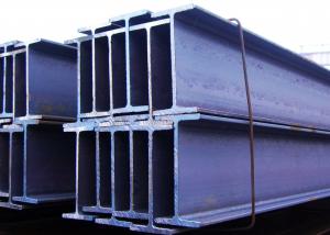
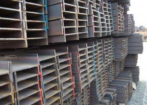
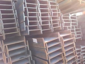
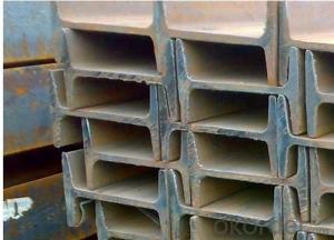
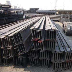
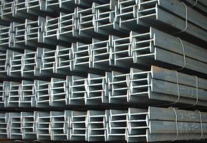
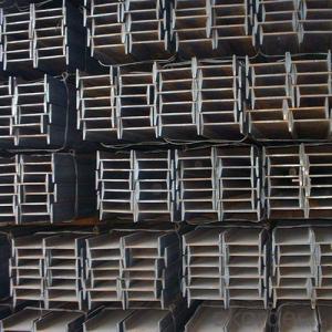
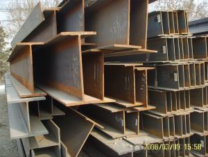
Carbon Mild Steel Universal Beam in I Shaped Form Chinese Standard Q235
- Loading Port:
- Tianjin
- Payment Terms:
- TT or LC
- Min Order Qty:
- 25 m.t.
- Supply Capability:
- 1000 m.t./month
OKorder Service Pledge
OKorder Financial Service
You Might Also Like
1. Structure of Carbon Mild Steel Universal Beam in I Shaped Form Description:
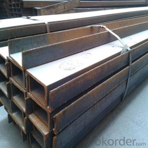
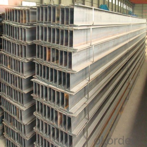
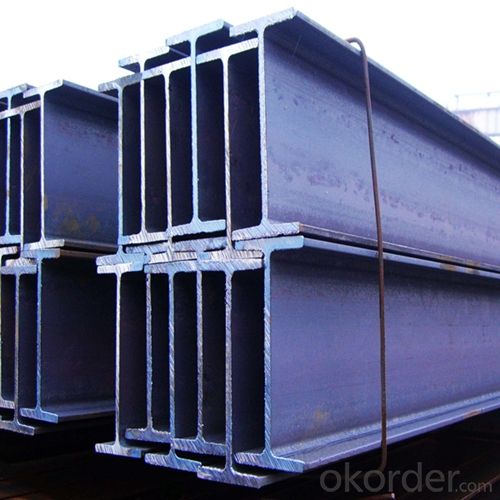
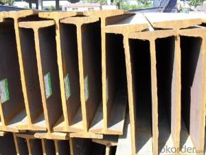
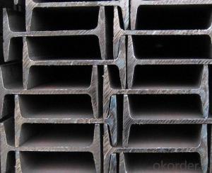
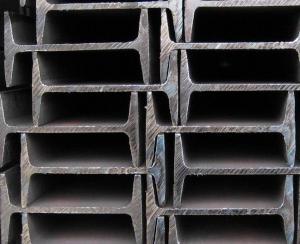
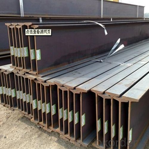
Carbon mild steel universal beam in I shaped form is a beam with an I-shaped cross-section. The horizontal elements of the "I" are known as flanges, while the vertical element is termed the "web". Carbon mild steel universal beam in I shaped form is usually made of structural steel and is used in construction and civil engineering. The carbon mild steel universal beam in I shaped form resists shear forces, while the flanges resist most of the bending moment experienced by the beam. Carbon mild steel universal beam in I shaped form theory shows that the I-shaped section is a very efficient form for carrying both bending and shears loads in the plane of the web.
2. Main Features of Carbon Mild Steel Universal Beam in I Shaped Form:
• Grade: Q235
• Type: Mild carbon steel
• Deflection: The stiffness of the I-beam will be chosen to minimize deformation
• Vibration: The stiffness and mass are chosen to prevent unacceptable vibrations, particularly in settings sensitive to vibrations, such as offices and libraries.
• Local yield: Caused by concentrated loads, such as at the beam's point of support.
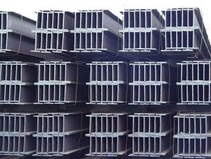
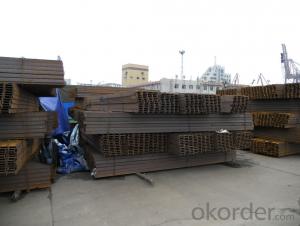
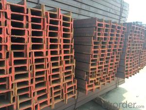
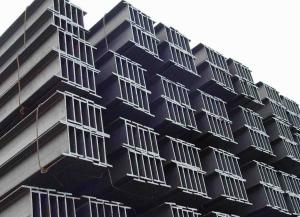
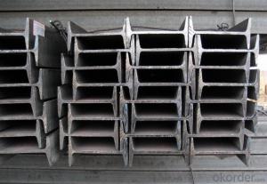
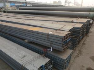
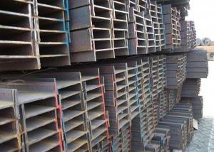
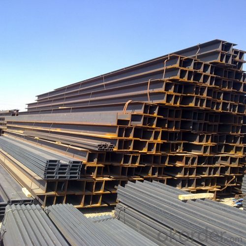
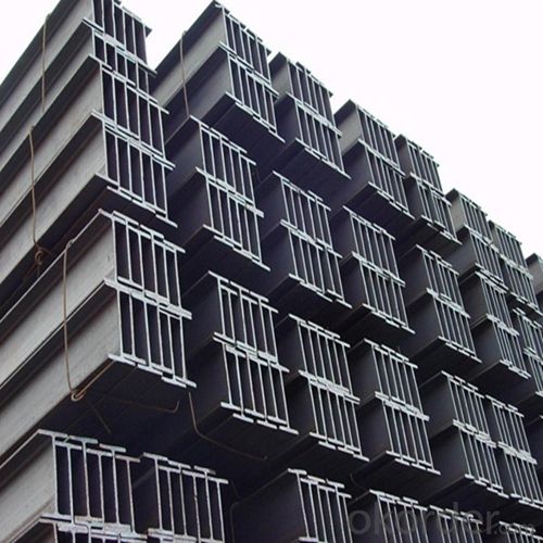
3. Carbon Mild Steel Universal Beam in I Shaped Form Images:
4. Carbon Mild Steel Universal Beam in I Shaped Form Specification:
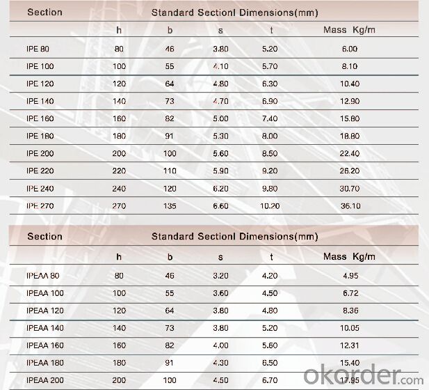
5. FAQ
We have organized several common questions for our clients,may help you sincerely:
①Is this product same as W beam?
In the United States, the most commonly mentioned I-beam is the wide-flange (W) shape. These beams have flanges in which the planes are nearly parallel. Other I-beams include American Standard (designated S) shapes, in which flange surfaces are not parallel, and H-piles (designated HP), which are typically used as pile foundations. Wide-flange shapes are available in grade ASTM A992,[4] which has generally replaced the older ASTM grades A572 and A36.
②How to inspect the quality?
We have a professional inspection group which belongs to our company. We resolutely put an end to unqualified products flowing into the market. At the same time, we will provide necessary follow-up service assurance.
③Is there any advantage about this kind of product?
Steel I beam bar IPE has a reduced capacity in the transverse direction, and is also inefficient in carrying torsion, for which hollow structural sections are often preferred.
- Q: What are the common connection methods for steel I-beams?
- Steel I-beams can be connected using different methods depending on the specific application and structural requirements. Some commonly used connection methods include: 1. Welding: Steel I-beams are often connected using welding, which involves melting and fusing the edges of the beams together using heat. This creates a strong and permanent bond. Welding can be done manually or using automated processes like robotic welding. 2. Bolting: Another common method is bolting, where bolts and nuts are used to secure the beams together. This method allows for easy disassembly and reassembly if necessary. 3. Riveting: Riveting involves using metal rivets to join the beams. Holes are drilled in the beams and rivets are inserted, then hammered or pressed to create a secure connection. Riveting was commonly used in the past but has been mostly replaced by welding and bolting due to the labor-intensive process. 4. Adhesive bonding: In specialized applications or situations where welding or bolting is not feasible, adhesive bonding is used. Industrial adhesives are used to bond the beams together. This method provides a strong and lightweight connection but may require additional surface preparation and curing time. It's important to consider various factors such as load-bearing capacity, steel type, structural design, and project constraints when choosing a connection method. Consulting with a structural engineer or following industry standards and regulations is crucial to ensure safe and effective connections for steel I-beams.
- Q: Can Steel I-Beams be used for mezzanine storage?
- Yes, steel I-beams can be used for mezzanine storage. Steel I-beams are commonly used in construction for their strength and load-bearing capabilities. They are ideal for supporting heavy loads and can withstand the weight of a mezzanine structure and the items stored on it. The I-beams can be securely bolted or welded into place to provide a stable and sturdy base for the mezzanine floor. Additionally, steel I-beams can be customized to meet specific design requirements and can be easily integrated into existing structures. Overall, steel I-beams are a reliable and efficient choice for supporting mezzanine storage systems.
- Q: How are steel I-beams used in construction?
- Steel I-beams are commonly used in construction as structural support elements. They are characterized by their distinctive I shape, which allows them to bear heavy loads over long spans. I-beams are positioned horizontally and are often integrated into the framework of buildings, bridges, and other structures to provide strength and stability. They can support walls, floors, roofs, and even entire buildings, making them an essential component in the construction industry.
- Q: How do steel I-beams perform in high-humidity environments?
- Due to their inherent resistance to moisture, steel I-beams perform well in high-humidity environments. Typically, the steel used in I-beams is coated with protective finishes like galvanization or paint. These finishes act as barriers to prevent moisture penetration and direct contact with water or humidity, thus preventing corrosion. Moreover, steel is a non-porous material, unlike wood or other organic materials. This non-porous characteristic makes steel I-beams less prone to swelling, warping, or rotting that can occur in high-humidity conditions. However, in extremely corrosive environments such as coastal areas with high salt content in the air, additional precautions may be necessary. In such cases, stainless steel or other corrosion-resistant alloys are commonly utilized to ensure the durability and performance of the I-beams. All in all, steel I-beams are a reliable choice for high-humidity environments. They offer strength, durability, and resistance to moisture-related issues.
- Q: What are the different types of steel finishes available for I-beams?
- There are several different types of steel finishes available for I-beams, each with its own unique properties and benefits. Here are some of the most common types: 1. Hot-dip galvanized: This is a popular finish that provides excellent corrosion resistance. The I-beams are dipped into a bath of molten zinc, which creates a protective layer on the steel. Hot-dip galvanized finishes are commonly used in outdoor applications where the beams may be exposed to moisture or harsh weather conditions. 2. Painted: Steel I-beams can also be painted to provide a protective barrier against corrosion. The paint acts as a barrier between the steel and the environment, preventing oxidation and rusting. Painted finishes are available in a variety of colors and can be customized to match specific aesthetic requirements. 3. Powder-coated: Powder coating is a durable finish that is applied as a dry powder and then cured under heat. This process creates a hard, smooth, and attractive finish that offers excellent resistance to chipping, scratching, and fading. Powder-coated finishes are available in a wide range of colors and can be tailored to meet specific design preferences. 4. Bare steel: In some cases, I-beams may be left untreated without any additional finishes. This is often seen in indoor applications or situations where the beams are not exposed to moisture or corrosive elements. Bare steel finishes provide a natural and industrial look, but they may be more susceptible to rusting over time. 5. Epoxy coated: Epoxy coatings are commonly used in industrial and marine environments where the I-beams are exposed to harsh chemicals or high humidity. The epoxy coating creates a barrier that protects the steel from corrosion and chemical damage. These finishes are highly resistant to abrasion, impact, and UV rays. It's important to consider the specific requirements of your project when selecting a steel finish for I-beams. Factors such as environmental conditions, desired aesthetics, and budget should all be taken into account to ensure the best choice for your application. Consulting with a steel specialist or engineer can help you determine the most suitable finish for your specific needs.
- Q: Can steel I-beams be painted or coated to match the desired aesthetics?
- Yes, steel I-beams can be painted or coated to match the desired aesthetics. Steel I-beams are commonly used in construction and industrial applications, where their strength and load-bearing capabilities are essential. However, their raw steel finish may not always be visually appealing or suitable for certain environments. To match the desired aesthetics, steel I-beams can be painted or coated using various methods. The surface of the beams needs to be properly prepared before painting or coating to ensure adhesion and durability. This typically involves removing any rust, dirt, or contaminants and applying a suitable primer. Once the surface is prepared, different types of paint or coating systems can be used. This can include industrial-grade paints, such as epoxy or polyurethane coatings, which provide excellent protection against corrosion and wear. These coatings can also be customized to achieve the desired color and finish. Additionally, powder coating is a popular method for aesthetic enhancement of steel I-beams. Powder coating involves applying a dry powder to the surface of the beams, which is then cured under heat to create a durable and attractive finish. Powder coating offers a wide range of color options and can provide a smooth, even, and uniform appearance. It is important to note that the choice of paint or coating system should consider the specific requirements of the application. Factors such as environmental conditions, exposure to chemicals or moisture, and the desired level of durability should be taken into account. Consulting with a professional painter or coating specialist can help ensure the best outcome in terms of aesthetics and performance.
- Q: What are the common challenges involved in working with steel I-beams?
- Working with steel I-beams can present several challenges. One common challenge is their weight and size. Steel I-beams are heavy and often require specialized equipment and machinery for transportation and installation. This can pose logistical difficulties and increase project costs. Another challenge is their rigidity. Steel I-beams are known for their strength and durability, but this inflexibility can make it challenging to accommodate changes or modifications during construction. Any alterations may require cutting, welding, or additional reinforcements, which can be time-consuming and costly. Maintaining structural integrity is also a challenge. Steel I-beams are susceptible to corrosion, especially in environments with high humidity or exposure to chemicals. Adequate coating and regular maintenance are necessary to prevent rust and ensure long-term durability. Additionally, steel I-beams often require precise measurement and alignment during installation to ensure proper load distribution and structural stability. Any inaccuracies or errors in measurement can result in structural issues or safety hazards. Fire resistance is another challenge. Steel I-beams have a high melting point, but prolonged exposure to high temperatures can weaken their structural integrity. Fire-resistant coatings or additional fire protection measures are often necessary to mitigate this risk. Lastly, cost can be a significant challenge when working with steel I-beams. Steel is generally more expensive than other building materials, so budget constraints may limit the use of steel I-beams in construction projects. Additionally, the fluctuating prices of steel can impact project budgets and timelines. Overall, while steel I-beams offer numerous advantages, including strength and durability, they also present challenges related to weight, rigidity, maintenance, alignment, fire resistance, and cost. Overcoming these challenges requires careful planning, expertise, and adherence to industry standards and best practices.
- Q: How do steel I-beams contribute to the overall cost-effectiveness of a construction project?
- Steel I-beams contribute to the overall cost-effectiveness of a construction project by providing a durable and efficient structural solution. Their high strength-to-weight ratio allows for lighter foundations and reduced material usage, resulting in lower construction costs. Additionally, their versatility and ease of installation save time and labor expenses, making steel I-beams a cost-effective choice for long-span structures and high-rise buildings.
- Q: What are the considerations for fire rating steel I-beams?
- There are several factors to consider when evaluating the fire rating of steel I-beams. First and foremost, the fire resistance of the I-beams is crucial. This is determined by the type and thickness of the fireproofing material applied to the beams. Common fireproofing materials for steel I-beams include intumescent coatings, which expand when exposed to heat and create an insulating layer to protect the steel from fire. It is important to ensure that the fire resistance rating of the I-beams meets the requirements set by local building codes and regulations. Another factor to consider is the load-bearing capacity of the I-beams during a fire. Although steel I-beams are designed to carry heavy loads, the high temperatures in a fire can weaken their structural integrity. Therefore, it is essential to ensure that the I-beams can withstand both the weight loads and the potential impact of a fire without compromising their stability. The fire protection system in the building should also be taken into account. This includes the presence of fire alarms, sprinklers, and other fire suppression systems that can help control or extinguish a fire. These systems provide additional protection to the steel I-beams and prevent the fire from spreading further. Furthermore, the fire rating of the steel I-beams should be compatible with the fire resistance of other building components, such as walls, floors, and ceilings. If the I-beams are supporting these components, they should have a fire rating that matches or exceeds the fire rating of the surrounding materials. Lastly, the intended use and occupancy of the building should be considered. Different occupancy types have different fire safety requirements, which may influence the necessary fire rating for the steel I-beams. For instance, buildings with high occupancy loads or those housing flammable materials may require higher fire resistance ratings for the I-beams. In conclusion, when evaluating the fire rating of steel I-beams, it is important to carefully assess factors such as fire resistance, load-bearing capacity, fire protection systems, building construction, and occupancy type. This ensures the safety and compliance of the structure.
- Q: In steel engineering, what is called rigid connection? What is articulated? What kind of nodes or structural parts are applicable to the two? The more detailed the answer, the better!
- Rigid connection refers to the connection between two members of a rigid joint.In steel structures, for example, the I-beam is rigidly connected, which means that the two flanges are connected to the flange and the web, while the hinge is just the web connection. The flange is not connected.
Send your message to us
Carbon Mild Steel Universal Beam in I Shaped Form Chinese Standard Q235
- Loading Port:
- Tianjin
- Payment Terms:
- TT or LC
- Min Order Qty:
- 25 m.t.
- Supply Capability:
- 1000 m.t./month
OKorder Service Pledge
OKorder Financial Service
Similar products
Hot products
Hot Searches
Related keywords
