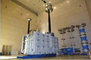

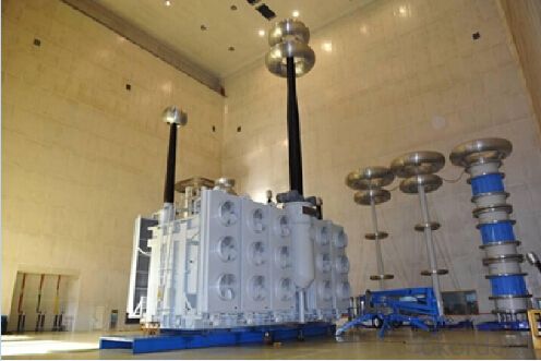
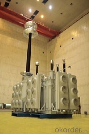
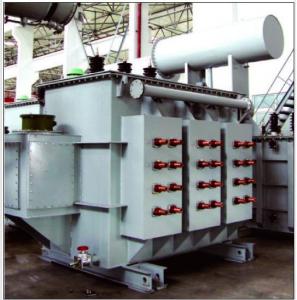
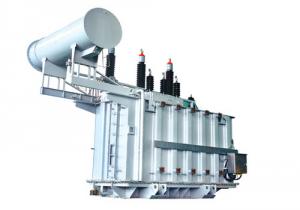
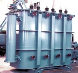
The world's first 1500MVA/1000kV UHV AC transformer
- Ref Price:
-

- Loading Port:
- Tianjin
- Payment Terms:
- TT OR LC
- Min Order Qty:
- 1 pc
- Supply Capability:
- 1 pc/month
OKorder Service Pledge
OKorder Financial Service
You Might Also Like


Quick Details
| Place of Origin: | HeBei | Brand Name: | CNBM | Model Number: | SFZ10-63000 / 110 |
| Usage: | Power | Phase: | Three | Coil Structure: | Toroidal |
| Coil Number: | 3 Winding | Capacity: | 50000 63000 80000 100000 120000 180000 | Rated Voltage: | 1000kV |
| Connection Symbol: | YNd11 Dyn11 YNyn0d11 | Tank: | Cover type or Bell type | OLTC: | MR or ABB or SMS |
Packaging & Delivery
| Packaging Detail: | Mainbody --naked Disassembled parts -- crate |
| Delivery Detail: | 3 months |
Specifications
1. CESI certificate
2. High short-circuit withstand
3. Low loss, PD and noise
4. CTQC certificate
5. No leakage
Description
The application of 1500MVA/1000kV AC UHV Transformer can significantly improve the economy of the UHV substation, and matches well with the transmission capacity of UHV lines, which has wide prospect of application. Because of its large capacity and large volume, the whole transportation weight with nitrogen is about 470-490 tons, and due to the restricted transport conditions, the transportation becomes the critical issue for application of the 1500MVA/1000kV UHV AC transformer. In order to make the products applicable to any UHV substation in our country, the state grid of corporation of China set the "A study of easy-transport large capacity UHV Transformer” as a key scientific research projects, and entrusted BTW to carry out the research.
During the process of research and development, BTW adopted the advanced design technology and modular design, the transformer can be transported disassembly and with advantages of compact core and winding body, less transportation weight and low transportation cost, effectively solves the need of UHV construction in the transportation restricted areas. By using the most advanced 3D magnetic field calculation software, BTW performed detailed analysis and calculation for the magnetic flux leakage and eddy current loss of the transformer coil, iron core and oil tank steel structures. Besides, by using of the advanced electric field calculation software, BTW performed detailed analysis and calculation of main longitudinal insulation, and mastered the arrangement of the main longitudinal insulation of large capacity UHV transformer and the control of distribution of winding magnetic flux leakage. All of which make the products with low loss, low noise, small volume, strong anti short circuit ability, no local overheating and other significant advantages, and guarantee the long-term safe and stable operation.
The world's first on-site assembled large capacity UHV Transformer’s right at the first time once again filled the gap in the field of UHV transformer research after Chinese transformer industry overcame the difficulty of integral transport of 1500MVA/1000k transformer, which marks BTW has fully occupied the world transformer industry technical peak. The successful development of the product filled the gaps in the domestic technology and met the urgent need of UHV construction application in our country, greatly improved the technical level and manufacturing ability of BTW in terms of UHV Transformer products.
- Q: I am doing a school project of a Wind Turbine; and I need to show a transformer or what a transformer is in a wind turbine. I have just 1 question. WHY DO PEOPLE USE TRANSFORMERS?
- Transformers are used to adjust voltage levels to reduce current and thereby reduce voltage drop in transmission lines.
- Q: 27. Two transformer A and B with identical ratings, are to be designed with fux densities of 1.2 and 1.4 wb/m2 respectively. The weight of transformer A per KVA is(a) More than that of transformer B(b) Less than that of transformer B(c) Equal to that of transformer B(d) None28. Transformer action requires which type of flux?(a) Pulsating magnetic flux(b) Constant(c) Increasing(d) Alternating electric flux29. In what capacity transformer natural oil cooling with tubes is used(a) 3000 KVA(c) 500 KVA(b) 30 KVA(d) 750 KVA30. In full rating of transformer is 90 KW at a pf of 0.9, then its KVA rating is(a) 100(c) 90(b) 150(d) 80
- 27. (a) More than that of transformer B 28. (a) Pulsating magnetic flux 29. I do not think there is such a limitation on ONAN transformers. 30. (a) 100
- Q: What is the difference between transformer MVA and KVA?
- MVA = 1000KVA Is the usual representation of the transformer capacity.
- Q: I used to live in the US but moved out to the Philippines. In the states the voltage out put is 110 but here in manila its 220. Because of this, all of my american electronics need transformers so they dont burn up or explode. Which one should I use on my TV. A Voltage Regulator (AVR) or a transformer? What in the heck is the difference anyway?
- now i know .what i need to refrigirator,,a transformer right?
- Q: I need to get a transformer that produces 12 watts. Problem is that I burned out the previous 2 I had with my hot wire cutter. I have a couple of 9 watt and 3 watt transformers. Is there anyway I can combine them together so that I can produce the desired 12 watts. I was thinking about rectifying to DC. Then putting the power sources in parallel to power my hot wire cutter. Is this a good idea or is there another way to do it.
- no, connecting two transformers together, unless they are identical, doesn't work. The one with the higher voltage will see the others as low impedances and try to drive them, with the result of a burned out transformer. But if you rectify each one to DC, the diodes will prevent the lower voltage ones from overloading the higher voltage one, but you will still have a problem in that the higher voltage one will be the only one delivering any power. .
- Q: Can a transformer having a given VA rating at 50Hz handle more power at a higher frequency, say, 300Hz or 400Hz?I want to build an inverter to run an 11 watt compact fluorescent lamp. Since these devices rectify the supply directly, there does not seem to be any good reason to feed the lamp with 50Hz.If my understanding is correct, the core has to be able to store up to one half-cycle's worth of energy in the magnetic field (which will then be released out of the secondary winding in the form of electricity) to avoid going into saturation and overheating. So at twice the frequency, it should be possible to push twice as much power through for the shorter half-period without saturating the core. (Actually, probably a little less than twice as much, as there will be more resistive heating; but transformer wire is often slightly thicker than it really needs to be, just because it's less likely to break in the winding machine.)So can I over-run a transformer this way, or is there some gotcha that I've missed?
- The equation V 4.44fNaB determines what is required for a transformer to avoid saturation. V is the voltage, f is the frequency, N is the number of turns of wire in the winding, a is the area of the core, and B is the peak magnetic flux density. The transformer has presumably been designed so that the peak flux density is as high as it can be without saturating the core. For an existing transformer, V/f a constant. If you increase f, you can increase V so that V/f remains constant. However, the hysteresis losses increase in proportion to the frequency increase and the eddy current losses increase in proportion to frequency squared. In addition, skin effect will increase the copper losses at higher frequencies. Reducing the copper losses by reducing the current would compensate for the skin effect. Reducing the copper losses would tend to compensate for the increased iron losses, but it is hard to say how much a cooler coil will compensate for a hotter core.
- Q: Hello, I am using a spark transmitting system that will throw about 40KV at about 5MA. I need to step this way down. What rating should I look for? If a current transformer isn't the way to go, please tell me what I should doThanks in advance
- Current transformer coupling the 40kv line then produce about a few hundred volts depending on how many turns existed in the current transmitter. It needs many such transformers to do different step down. If you require over 5kv per step,current transformer coupling might not be the best way. The better way is control the high voltage 40kv source.Vary the supply source shall do.
- Q: LED non-isolated drive transformer (two windings) calculation method
- General non-isolated auxiliary windings according to chip drop VCC operating range. T = 1 / f Dmin = Vout / Vin (max) Ton = T * Dmin Id = Io * 0.3 (0.3 for the ripple current coefficient) Inductor voltage V = Vinmin-Vout-0.6 (Schottky voltage drop) Lmin = V * dt / di If there are problems please go to the big bit of the forum electronic transformer plate
- Q: about transformers
- Your logic is valid but a careful look will tell what is happening. This strange behaviour is not that uncommon, it has analogy in other areas also. For example when you push a large stone, it is pushing you back (famous third law), then how does it move at all, if it cancels the supply force? On the other hand when you push a strong wall, it reacts with equal and opposite reaction. The thing is if the wall did not exert this reaction it would have allowed itself to be pushed back without any resistance!! These action / reaction like, supply voltage and induced emf (other examples are terminal volt of a d c motor and back emf, generator output and its reaction on prime mover etc etc) are all must be conceptually understood. I can dare say that they do not exist as such! They are merely way of understanding the concepts. When you supply ac volt to a coil (transformer without secondary load is just a coil) because of energy transformations taking place we see that the coil offers resistance much different from pure resistance, which is called impedance. But the same can be viewed as reduction of available voltage due to induced emf. I repeat this is a conceptual understanding of the phenomenon.
- Q: 1.Transformers are normally used to step up or step down alternating voltage or current. May dc also be used to step up or step down voltage or current? Motivate your answer?2.The supply voltage of a step down transformer is 240 volts and the winding ratio is 4,8 : 1. If there are 2000 turns on the primary winding calculate:2.1) The number of turns on the secondary2.2) The primary current when the secondary current is 15 A3. Calculate the secondary voltage of a transformer with supply voltage of 415 volts, the winding ration is 36 : 14.Can an Autotransformer be used to step up pulsating dc current? Motivate your answer.
- 1.strictly NO.DC cannot be used at all to step up and step down using transformer if you read the working of transformer,it works on the principle of electromagnetic induction. i.e. it depends on change of flux with time. it can only happen in ac voltages not in dc ones because in dc the volatge is fixed but in ac it changes with time and flux and current are directly proportional. 2. 2.1)it is step down transformer. so number of turns in primaryno. of turns in secondary NpNs 4.8/12000/Ns Ns2000/4.8 Ns416.6777 but no of turns needs to be an integer so Ns417 (round off) 2.2)Ip/IsNs/Np IpIs*Ns/Np 15*2000/417 71.94A 3) 415/Vs36/1 Vs11.53V 4) Yes. such transfomers are called pulse transformers.
Send your message to us
The world's first 1500MVA/1000kV UHV AC transformer
- Ref Price:
-
- Loading Port:
- Tianjin
- Payment Terms:
- TT OR LC
- Min Order Qty:
- 1 pc
- Supply Capability:
- 1 pc/month
OKorder Service Pledge
OKorder Financial Service
Similar products
Hot products


Hot Searches
Related keywords

