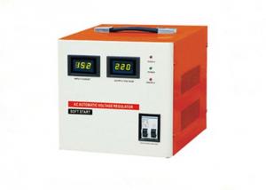
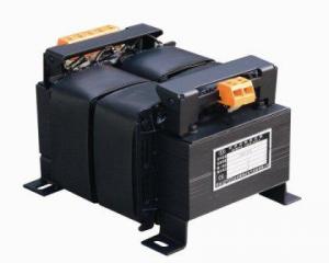
SVC LEDThree Automatic Voltage Stabilizer
- Loading Port:
- Shanghai
- Payment Terms:
- TT OR LC
- Min Order Qty:
- -
- Supply Capability:
- 10000pcs pc/month
OKorder Service Pledge
Quality Product, Order Online Tracking, Timely Delivery
OKorder Financial Service
Credit Rating, Credit Services, Credit Purchasing
You Might Also Like
1.Application
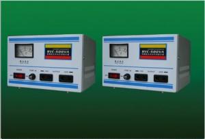
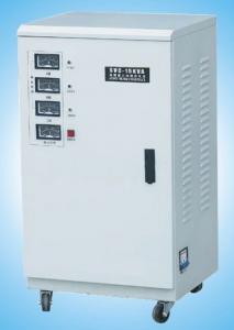
SVC(LED)(Three) automatic regulator voltage consists of contact voltage regulator,sampling control circuit and servomotor as well.It has excellent features,such as small waveform distortion,high efficiency,high power factor,free from the effect or frequency variation of supply. It can be widely used in most situations where the voltage stabilization is required.
2. Specification
| Input voltage | 280V-430V |
| Output voltage | 380V±3% |
| Phase | Three phase |
| Frequency | 50Hz/60Hz |
| Response | 1 sec. (against 10% input voltage deviation) |
| Efficiency | Better than 90% |
| Ambient temperature | -10oC~+40oC |
| Relative humidity | Less than 90% |
| Waveform | Non-lack fidelity waveform |
| Insulation resistance | >5MΩ |
3. Outline and packing
| Type | Outline(cm) | Weight(Kg) | Qty/CTN | ||
|---|---|---|---|---|---|
| L | W | H | |||
| SVC-D1.5KVA-3 | 48.5 | 22.5 | 17 | 16.5 | 1PCS |
| SVC-D3KVA-3 | 48.5 | 22.5 | 17 | 24 | 1PCS |
| SVC-D4.5KVA-3 | 48.5 | 22.5 | 17 | 25 | 1PCS |
| SVC-D6KVA-3 | 39 | 31.5 | 77 | 36.5 | 1PCS |
| SVC-D9KVA-3 | 43.5 | 36 | 77 | 49.6 | 1PCS |
| SVC-D15KVA-3 | 48 | 36 | 70 | 65.5 | 1PCS |
| SVC-D20KVA-3 | 51.5 | 40.5 | 85 | 88 | 1PCS |
| SVC-D30KVA-3 | 59 | 46 | 109 | 108 | 1PCS |
| SVC-D40KVA-3 | 64.5 | 52.5 | 109 | 190 | 1PCS |
| SVC-D50KVA-3 | 64.5 | 52.5 | 109 | 203 | 1PCS |
| SVC-D60KVA-3 | 64.5 | 52.5 | 109 | 210 | 1PCS |
| SVC-D75KVA-3 | 67 | 56.5 | 130 | 240 | 1PCS |
| SVC-D100KVA-3 | 67 | 56.5 | 130 | 260 | 1PCS |
- Q: I have two questions about electrical transformers1.Do all transformers come with wires so I can hook it up and plug it into a wall? If not, where can I get those?2.If I don't have anything to sauter wires, could I use eletrical tape instead? Which sounds sloppy.
- 1. Transformers don't usually have plugs on them. 2. The word you want is solder. Tape will work, but it is sloppy.
- Q: Hi, thanks for reading my question. I'm an electrician with some basic knowledge of electricity but this is puzzling me. In the USA, a single transformer on a pole means split phase. Three transformers on a pole means 3 phase. What does two transformers mean? Is it split phase with a high leg?Thanks
- In my area there are sometimes 3 or four transformers on a pole. This is a residential area though and a lot of the houses use electrical resistance heating. Looking at the transformers on the nearest pole I see see two wires output and a ground cable coming from each transformer. The transformer coming to my home is single phase 240 volt ( 120V on each hot line). The transformers are rated at 50 kva, so I'm assuming four 50 kva transformers was probably cheaper and more flexible than using one 200 kva transformer.
- Q: how do i work out the voltage output of the second winding on a transformer if i know the Primary voltage is 35v and the first winding has 355 windings and the second winding has 4500 how do you do this ?thanks
- Assuming that the transformer is designed for a primary voltage of 35 or more, then you can simply multiply the applied primary voltage (up to the design limit) by the turns ratio and this will give you the output voltage. In this case: output voltage 35 x 4500/355 444.
- Q: Transformers of the three transformations are the three?
- Take a 10kV / 0.4kV, d / yn11, 100kVA transformer rated voltage full load operation: 1, the high side of the 10kV into the low side of the 400V; 2, the high pressure of 5.77A into low pressure side of 144.4A;
- Q: As we switch off an appliance at home, the power supply is cut off.when we switch it on , the power is on.How does the transformer regulate /manage as per our requirement
- 1. You haven't specified your requirement. 2. Transformers don't regulate. Regulate is the job of a voltage regulator chip, like the LM7805. 3. Transformers don't manage either. People manage. People can also program computers to manage switches. Transformers just sit there, waiting for a closed loop for current flow on both primary coil and secondary coil. When both loops are closed, energy is transferred from one coil to the other by magnetic induction. When either loop is open, current ceases in the open coil, but still creates an alternating magnetic field in the closed loop, if the closed loop is the primary.
- Q: I'm 13 and I love the Transformers movie, TF Animated and TF Armadaactually, those are the only ones I HAVE seen so farI'm just wondering where to start with attempting to watch them all? And in what order? Or, doesn't it matter? I suppose it does with G1 and 2Where on the internet can I watch them? Any recommendations?Please answer! I really want to have seen every one!
- not okorder
- Q: given that volts x amps watts why dont they just rate a transformer by kilowatts. I havent been able to link the logic behind rating a transformer by KVA, but there must be a reason. If you think you can help me I am eager to learn and will appreciate your help.
- Mick Johnson and Mike Roberts asked the same question. You should see their answers side by side.
- Q: I want to make a simple flyback transformer driver. I have a flyback transformer of samsung CRT monitor. Can anyone give me a complete design of flyback transformer's pin. What are the required components. Please give answer in detail.
- These transformers are designed for TV or monitor line frequency. They use a square wave drive at the line frequency (15625Hz or more for a monitor) The on time is around half the duration of a cycle or more, so 32us for 15625Hz. The driver is a switch, it is on for this time. The current builds as a sawtooth (ramping) current in the inductance of the winding during this time. The design of the driver switch needs to take into account ratings are in the safe operating area (SOA). This means the rate of change of voltage and current, as well as the instantaneous V * I must always be within ratings. It means that the switch should be rapid, so there is minimal time spent in the transition off to on and on to off. There usually needs to be a snubber network to control voltages across the transistor. The pin connections of the transformer? The links below show how to do it basically. It also shows how to check out and identify the windings you need, and also to verify them, using the schematic of the original device if possible. Tracing wires on the circuit board can help too, to identify the primary. You only need to identify 4 pins usually. There are some safety issues here. Some have small internal capacitors that store energy. This can give an unpleasant shock. It could be around 0.2 joules or more because of the high voltage. I am not sure what sort of a hazard this might be, but I wouldn't take it too lightly or use it to shock yourself or others. I assume you are using a 12V DC supply @ a few amps current to power this.
- Q: Why the provisions of the maximum temperature of the provisions of the transformer 65 °?
- Transformers and other electrical equipment temperature limit is determined by the level of insulation materials. Insulation grade refers to the heat resistance of the insulation material used, divided into A, E, B, F, H grade. Allowable temperature rise is the limit of the temperature of the electrical equipment compared to the ambient temperature. Insulation temperature class A grade E grade B grade F grade H grade Maximum permissible temperature (° C) 105 120 130 155 180 Winding temperature limit (K) 60 75 80 100 125 Performance reference temperature (° C) 80 95 100 120 145 In the electrical equipment such as transformers, the insulating material is the weakest link. Insulation material is particularly susceptible to high temperature and accelerated aging and damage. Different insulation materials have different heat resistance, the use of different insulation materials, electrical equipment, the ability to withstand high temperatures are different. So the general electrical equipment is specified in the maximum temperature of its work. You ask the question, the top of the oil temperature does not exceed 65 ℃, is in the case of rated load manufacturers consider a variety of factors to ensure that the insulation material is not damaged by the temperature limit. Under normal circumstances the top of the transformer oil temperature is the highest.
- Q: If it is powered by a DC source, will there be a Back EMF generated? Why/Why Not?Obviously, there will be a higher current flowing than that of a AC supplied transformer, but I don't know why.Thanks.
- Direct current (DC) is not transformed, as DC does not vary its magnetic fields
Send your message to us
SVC LEDThree Automatic Voltage Stabilizer
- Loading Port:
- Shanghai
- Payment Terms:
- TT OR LC
- Min Order Qty:
- -
- Supply Capability:
- 10000pcs pc/month
OKorder Service Pledge
Quality Product, Order Online Tracking, Timely Delivery
OKorder Financial Service
Credit Rating, Credit Services, Credit Purchasing
Similar products
Hot products
Hot Searches
Related keywords
