


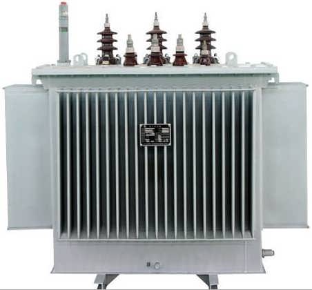
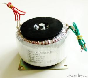
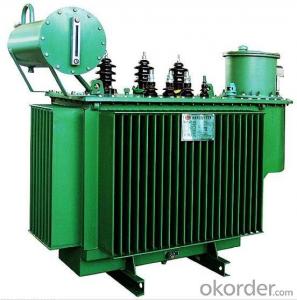
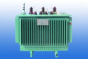
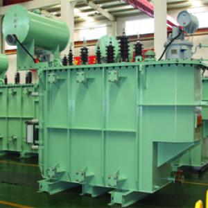
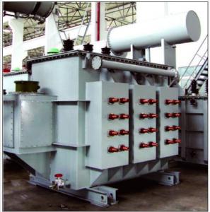
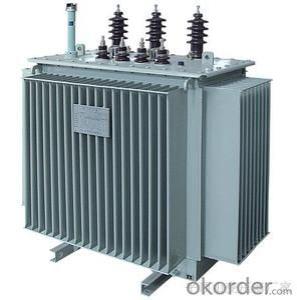
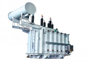
Class 10KV S11-M series transformer
- Ref Price:
-

- Loading Port:
- Shanghai
- Payment Terms:
- TT OR LC
- Min Order Qty:
- -
- Supply Capability:
- 1000sets set/month
OKorder Service Pledge
Quality Product, Order Online Tracking, Timely Delivery
OKorder Financial Service
Credit Rating, Credit Services, Credit Purchasing
You Might Also Like


| Rated capacity (KVA) | Voltage | connection group tab | Loss | unload current(%) | resistant voltage | weight | Measure(MM) | Distance of Din rail | |||||||
| high-voltage(kv) | extend connection | low-voltage(kv) | unload | load | empty weight | oil weight | total weight | length(L) | width(W) | height(H) | cross(M)×length | ||||
| 30 | 6 | ±5% (±2×2.5%) | 0.4 | Yyn0 | 100 | 600 | 2.1 | 4 | 205 | 80 | 360 | 755 | 700 | 970 | 400×400 |
| 50 | 130 | 870 | 2.0 | 260 | 85 | 420 | 785 | 735 | 995 | 400×450 | |||||
| 63 | 150 | 1040 | 1.9 | 325 | 110 | 535 | 1150 | 700 | 1130 | 400×450 | |||||
| 80 | 180 | 1250 | 1.8 | 330 | 90 | 505 | 815 | 755 | 1035 | 400×450 | |||||
| 100 | 200 | 1500 | 1.6 | 380 | 100 | 570 | 830 | 775 | 1040 | 400×450 | |||||
| 125 | 240 | 1800 | 1.5 | 430 | 105 | 645 | 845 | 770 | 1100 | 400×550 | |||||
| 160 | 280 | 2200 | 1.4 | 495 | 115 | 725 | 875 | 780 | 1115 | 550×550 | |||||
| 200 | 340 | 2600 | 1.3 | 570 | 130 | 845 | 1160 | 740 | 1135 | 550×550 | |||||
| 250 | 400 | 3050 | 1.2 | 670 | 150 | 1010 | 1270 | 840 | 1160 | 550×550 | |||||
| 315 | 480 | 3650 | 1.1 | 785 | 165 | 1135 | 1220 | 775 | 1220 | 660×660 | |||||
| 400 | 570 | 4300 | 1.0 | 935 | 190 | 1375 | 1350 | 895 | 1265 | 660×660 | |||||
| 500 | 680 | 5150 | 1.0 | 1100 | 215 | 1580 | 1395 | 905 | 1325 | 660×660 | |||||
| 630 | 810 | 6200 | 0.9 | 1315 | 250 | 1905 | 1465 | 980 | 1355 | 660×660 | |||||
| 800 | 980 | 7500 | 0.8 | 4.5 | 1655 | 310 | 2360 | 1555 | 995 | 1465 | 820×820 | ||||
| 1000 | 1150 | 10300 | 0.7 | 1835 | 355 | 2710 | 1715 | 1160 | 1525 | 820×820 | |||||
| 1250 | 1360 | 12000 | 0.6 | 2185 | 410 | 3200 | 1790 | 1235 | 1585 | 820×820 | |||||
| 1600 | 1640 | 14500 | 0.6 | 2490 | 500 | 3845 | 1830 | 1300 | 1670 | 820×820 | |||||
- Q: A 120 kVA, 7000/277 V (What does this rating mean) distribution transformer has the following resistances and reactances: Rp 5.5 ohms Xp 6.5 ohms Rs 0.007 ohms Xs 0.008 ohms Rc 55 kohms Xm 15 kohms The excitation branch impedance are given referred to the low voltage side of the transformer: a) What's the equivalent circuit of the transformer referred to the low voltage side b) What's the the per unit equivalent circuit c) Assume that this is supplying rated load at 277V and 0.89 lagging power factor, What is the transformer input
- 120 kVA, 7000/277 V (What does this rating mean) Primary voltage rating: 7000 V, secondary voltage rating: 277 V, rated load: 120 kVA It is unclear whether this is a single-phase or three-phase transformer. You probably need to assume it is single-phase. The equivalent circuit of a 3-phase transformer is analyzed as one of three single-phase transformers that could be connected to make the equivalent Y-Y three-phase transformer. The secondary voltage, 277 V, is the line to neutral voltage for a 480 V, wye distribution system. That is a USA standard system voltage. The primary would be 12,124 V L-L, 7000 V L-N. That would a reasonable primary distribution system voltage. Referring the circuit to the low side means changing the primary component values to the equivalent secondary values and moving the ideal transformer to the primary side of the circuit as shown below. To change the primary impedance values, multiply by (Sec V/Pri V)^2.
- Q: How do I determine if a transformer is beyond the normal temp range and is at risk of failure?A 225 kva installed in 1996 is running hot. I removed the cover and using a digital thermal meter read approx 125 degrees F on each winding. 243 degrees F on the top metal (winding support) frame. It's got parallel 750's off the load side and would be an expensive and difficult change.
- The first think you need to do is determine what the transformer's ratings are. The fact that i's nominally a 225kVA unit is only part of the story - what kind of insulation does it have, and what is the overtermperature capability of that insulation? Second, you need to determine what kind of cooling the transformer has, and whether that cooling is working properly. Some transformers are cooled only by exposure to ambient air, while other transformers are equipped ;with fans to blow air across cooling fins. Measuring the temperature of the coils using an external thermometer isn't appropriate - the limitation on transformer is the temperature internal to the winding. Is the transformer equipped with an interman temperature sensor? If not, then you can only base you conclusion on loading. I don't know what you mean when you say parallel 750's off the load side. You will need to determine the loading on the transformer, and compare that with the full rating of the transformer including any adjustment for cooling and ambient air temperature.
- Q: i have been looking at transformers and i wanted to know a few things. will they do dc current? do they just add x amount of volts or do they multiply by x or just change to x? also there is a sort of container that goes around them is that carbon???? it goes all the way around and then through
- It is the reversal of polarity that induces a voltage, therefore only AC. It is the number of turns ratio that determine the voltage of output. It will be the same power (minus transformer losses) in and out. If the number of turns causes a stepped down voltage the current will increase by the same measure.
- Q: What does S11-M-500/10 transformer mean?
- The first floor has been very accurate to answer my answer that M is sealed!
- Q: I'm a good Transformers fan, but i've only really watched the more recent shows like armada, energon, etc. so i'm confused with some things in the new movie:1. Is Jetfire really supposed to be that old?2. Jetfire mentioned the Optimus must be the last decendent of the Primes? is Omega Prime one or no?3. When the Fallen appeared in the comic where he first showed up, did he have the same power over Megatron4. Did anyone else notice that Ratchet just showed up during the forest battle scene?5. Did Megatron transform into both the cybertronian tank and plane in the movie?6. Anyone else find the Twins insainly rascist?7. Is Wheelie supposed to be a small toy in the universe?8. Is the human changing robot really in the series or just the movie?9. Can Constructicons really morph with each other to make a giant?10. Is Starscream the one that eventually switches to the Autobots?11. Does the Decepticon attaching itself to the sattlelite have a name?Thank You for clearing things up
- 1. No Jetfire isn't that old. although his age might be a little higher than others. 2. Omega Prime is a fusion of Optimus Prime and Ultra Magnus. So technically the answer is yes and no because it's actually Optimus Prime fused with another transformer. 6. Not really. It was just extremely stereotypical and a little annoying. But if you think that all stereotypical representations in movies are racist, then you'll have a problem watching any movie. Take asian stereotypes for example. 8. Pretenders (what the human changing robot is called) were first conceived in 1988, I think by Marvel Comics not sure about that. And yes it was in the Marvel Comics production of Transformers cartoons. 9. Yes, in the cartoon series they were able to merge into a larger Transformer called Devastator. 10. No, Starscream always tried to take control of the Decepticons behind Megatron's back or when Megatron is injured (eventually he is killed by Megatron-turned Galvatron). Jetfire is the Transformer that switched sides from the Decepticons to the Autobots. 11. The Decepticon's name is Soundwave.
- Q: If a transformer is rated for a maximum winding current of 10A, would it be permissible to operate it with 10A of input current when the secondary voltage to the load is 40V? Can you explain to me why?The information on the auto transformer plate wasInput 240V/ 50/60 cy 3HPoutput 0-240/280V 20 ampsThe parallel load resistance is 34.5 ohms
- It's simpler than you think. If an auto transformer has a rating of 10A, it doesn't matter if it's 10A at 280V or 10A at 2.8V. The current rating is based on the the size of the wire used to wind it along with the wiper contact characteristics. The core doesn't care about the voltage, only the current. So if you want maximum power transfer from an autotransformer, feed it across the winding ends with the full rated voltage (in this case, 280VAC), which will allow you to draw 10A * whatever voltage you have it set at in watts. And of course, yes you can set it to 40V at 10A, as long as your input voltage is anything higher than 40V (if it is not, the step-up action will cause higher than 10A to flow through the portion of the winding that the input is across).
- Q: I took apart a wall transformer before and soldered a single AA battery to the outputs and touched the what was before inputs and it gave me a shock. This is because it stepped up the power to something like 113v. Could I instead of a AA battery use 110 from the wall. Would it do the same thing. Or would it just overheat the transformer. And what would the amps be. I’m trying to make like a 20amp welder for just screwing around with.
- A standard transformer can step up the volts, sure. It's the basic isea behind things like a Tesla coil. It can also kill you. It's the volts that jolts, but its the mills (milli amps) that kills. A battery can't provide enough oomph to kill you. A 110v wall connection will do it without breaking a sweat. The small transformer might fizzle, buit that will be small comfort to those who find your corpse.
- Q: Transformer short-circuit impedance is big good, or small good? The same capacity, voltage ... solution
- Can not simply say big or small good because of the big, in the normal operation of the loss of certain size, in the short circuit. Short-circuit current will be great, less investment protection equipment corresponding to the requirements of the money so much to be more economic comparison Caixing! Can not be generalized, the choice of different transformers, impedance voltage is not the same; national transformer standard series, the general 10KV distribution transformer impedance of more than 5%, 35KV transformer impedance of more than 8%, 110KV transformer impedance In the 10% or so, the greater the capacity, the greater the impedance; transformer impedance increases, you can effectively reduce the size of short-circuit current, so in high voltage, high-capacity transformers, multi-purpose high-impedance or series reactor To reduce the short-circuit current, or some equipment is not a good choice; but the transformer impedance increases, the transformer will increase the volume, material consumption increases, the transformer running loss increases, but also to reduce the transformer secondary voltage, Is the transformer overload, the voltage will quickly decline, in case of short circuit conditions, may cause other equipment, low voltage action; under normal circumstances, or use the standard design of the transformer products, unless the special needs, do not use non-standard products, or in the Transformer side by side, selection, testing, maintenance, replacement will cause additional trouble.
- Q: hey all , i have 2 phase welding machine fed from 30A 3 phase circuit breaker , at high loads above 40A CB cut off the Supply . the problem is i cant change the CB size bcoz it Contrary to legislation in the country . Can i used scott t transformer to balance the load at the main 3 phase ?
- you're starting to be to be meant a single section welding device. This unit includes 2 supply lines. those lines may be linked to any 2 lines of a three-phse ability supply device.only connect one line to L1 and the different line to L2, only examine the line to line voltage of the flexibility supply. It must be the comparable by way of fact the welding device score, say, 380VOLTS, 50 Hz.
- Q: I need a transformer that can produce 10 volts from a 1/2 volt change in the primary winding, but don't know how they are classified. The transformers I've seen on the internet give no clue of the winding ratio, just a serial number. Thanks.
- I have never ordered a replacement transformer but you are looking to step the primary up 20 times and that is doable. I built a 1 Kilowatt amplifier for my ham radio station and my transformer steps the line voltage (either 120 or 240 volts) up to 3400 volts @ 500 mills. I also have a separate winding which steps the voltage down to about 9.6 volts for the tube filament. Aside from finding the correct step up ratio you also need to make sure the transformer can handle the power you will be dissipating. My transformer weighs about 25 pounds to allow the amp to put out about 1 KW. Wish I could've helped u more but I built the thing 15 years ago and have not fired up the amp in about 5 years.
Send your message to us
Class 10KV S11-M series transformer
- Ref Price:
-
- Loading Port:
- Shanghai
- Payment Terms:
- TT OR LC
- Min Order Qty:
- -
- Supply Capability:
- 1000sets set/month
OKorder Service Pledge
Quality Product, Order Online Tracking, Timely Delivery
OKorder Financial Service
Credit Rating, Credit Services, Credit Purchasing
Similar products


Hot products

Hot Searches
Related keywords

