

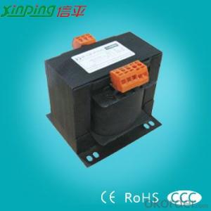
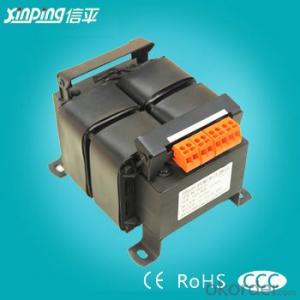
BK series machine tools control transformers
- Ref Price:
-

- Loading Port:
- Shanghai
- Payment Terms:
- TT OR LC
- Min Order Qty:
- -
- Supply Capability:
- 10000pcs pc/month
OKorder Service Pledge
OKorder Financial Service
You Might Also Like


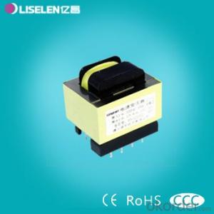
1.Application
BK series machine tool control transformer is suitable for circuit of 50~60Hz, voltage up to 500V, usually applied as power supply for machine tool electrical appliances, local lightings and indicator lamps.
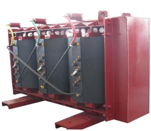
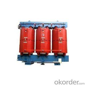
2.Structure character
According to different structures, BK transformer belongs to shell type, and according to the installation mode, it belongs to vertical type.
3.Working environment
1.Ambient air temperature: -5oC~+40oC, the highest monthly mean temperature should not exceed +30oC;
2.Altitude for installing place should not exceed 1000m;
3.When the ambient air temperature is +40, the relative humidity should not exceed 50%, and it allows higher relative humidity under lower temperature. Max average humidity in the dampest month is 90%, meanwhile the lowest average temperature of this month is +25oC, and condensation on the product surface caused by temperature change should be taken into consideration.
4.Specification
| Model | Overall size(mm) | Hole distance for installation(mm) | Installation hole (mm)K x J | |||
|---|---|---|---|---|---|---|
| Bmax | Dmax | Emax | A | C | ||
| BK-50 | 76 | 76 | 83 | 61±0.4 | 54±3 | 5 × 12 |
| BK-100 | 84 | 92 | 100 | 70±0.4 | 60±2.5 | 6 × 12 |
| BK-150 | 96 | 105 | 110 | 80±0.4 | 62±2.5 | 6 × 12 |
| BK-250 | 105 | 120 | 125 | 88±0.4 | 73±3 | 9 × 11.5 |
| BK-300 | 115 | 125 | 125 | 95±0.4 | 76±3 | 9 × 11.5 |
| BK-400 | 120 | 130 | 130 | 100±0.4 | 80±3 | 9 × 11.5 |
| BK-500 | 134 | 144 | 150 | 100±0.4 | 86±3 | 9 × 11.5 |
| BK-700 | 150 | 150 | 158 | 125±0.4 | 100±3 | 9 × 11.5 |
| BK-1000 | 150 | 153 | 160 | 125±0.4 | 110±3.5 | 9 × 11.5 |
| BK-1500 | 160 | 240 | 137 | 134±0.4 | 116±3.5 | 9 × 11.5 |
| BK-2000 | 189 | 270 | 145 | 158±0.4 | 122±3.5 | 9 × 11.5 |
| Type | Outline(mm) | Mounting size(mm) | Primary voltage | Secondary voltage | Weight(kg) | QTY/CTN |
|---|---|---|---|---|---|---|
| BK-25VA | 76×80×75 | 63×44 | 220V 380V | 380V,220V,110V,36V,24V,12V,6V (TO BE CHOSEN) | 1.97 | 16 |
| BK-50VA | 85×90×80 | 71×61 | 3.3 | 16 | ||
| BK-100VA | 103×92×95 | 87×69 | 5.5 | 12 | ||
| BK-150VA | 103×100×95 | 87×76 | 6.4 | 8 | ||
| BK-200VA | 103×106×95 | 87×81 | 7.3 | 8 | ||
| BK-250VA | 115×110×130 | 95×84 | 9 | 6 | ||
| BK-300VA | 115×115×130 | 95×86 | 9.87 | 6 | ||
| BK-400VA | 134×132×150 | 107×93 | 13.9 | 4 | ||
| BK-500VA | 134×137×150 | 107×98 | 15.5 | 4 | ||
| BK-1000VA | 153×149×168 | 128×115 | 25 | 2 | ||
| BK-1500VA | 175×185×185 | 140×135 | 17 | 1 | ||
| BK-2000VA | 175×195×185 | 140×145 | 21 | 1 | ||
| BK-2500VA | 207×250×230 | 168×163 | 25 | 1 | ||
| BK-3000VA | 207×250×230 | 168×173 | 28 | 1 | ||
| BK-4000VA | 240×240×250 | 200×160 | 40 | 1 | ||
| BK-5000VA | 240×250×250 | 200×170 | 41 | 1 |
- Q: I have a 150 watt bank of photovoltaic cells that run at 12 volts (PWM mode non-mppt charge controller). My question is, by substituting a dc transformer (one that boosts current and steps down to 12v) for a current boosting mppt, can I run the solar panels at their full rating even though they are connected to a 12 volt battery bank? The 12v batteries, when directly connected to the solar panels, drop the output because the panels output their full current at a higher voltage.I am also wanting to apply this logic to a wind turbine that outputs a maximum of 30 volts dc. I am thinking that if the switching transformer works for the solar panels, it would also work to step down the wind turbine's harsh dc voltage to a current boosted 12v state. Would this theoretically work?
- Transformers don't work on DC. You need a DC to DC converter.
- Q: 10 (6) What is the meaning of 10 and 6 in the KV transformer?
- Are the high voltage side of the input voltage were 10KV and 6KV units of kilovolt
- Q: anyone else see the trailor for this movielooks kinda goodthough, it may be were the transformers are bad guys, i dunno
- Ehhhh I'm not sold on the concept yet. I want to see a real finished transformer first. I'm sure they'll get the transforming part right, but the sound I think will be wrong and stupid, and they'll probably look like those robots from Sky Captain
- Q: What is the meaning of the transformer without excitation?
- No excitation refers to the transformer should be off the state of the power regulator, and his relative to the excitation voltage regulator should be on-load regulation.
- Q: 1. If the input voltage is 100V and output voltage is 200V, which side of the transformer winding will be primary?(a) 100V side (c) winding with loss turns(b) 200V side (d) winding with more turns2. Which of the following statement about humming of transformer is true?(a) The frequency of humming tone is 100Hz(b) The frequency of humming tone is 50 Hz(c) The humming is caused by a vibration of the low voltage winding through which the high current flows(d) The humming is caused by the private force of attraction between the lamination of the core3. In a 10 KVA, 230/1000V 1-? transformer, the no load current will be around(a) 3 A(c) 10 A(b) 0.5 A (d) 0.9 A
- A transformer can be used as step-up or step-down, but normally use is as step-down so b. for the first question. Second question, the humming is caused by d. and will be at the frequency of the supply. Third question would be b. or d. since the only current drawn on no-load is the magnetising current for the core.
- Q: i can't seem to think of the name or artists of this song. All I could remember it has transformer lyrics (not the theme song). it has an old school hip hop/rap vibe to it but i need help of what's the name of it, thanks!!!
- Kurtis okorder
- Q: I took apart a wall transformer before and soldered a single AA battery to the outputs and touched the what was before inputs and it gave me a shock. This is because it stepped up the power to something like 113v. Could I instead of a AA battery use 110 from the wall. Would it do the same thing. Or would it just overheat the transformer. And what would the amps be. I’m trying to make like a 20amp welder for just screwing around with.
- You will blow fuses DO NOT TAMPER WITH THINGS YOU DON'T UNDERSTAND a primary winding has enough turns to reduce magnetizing current to a few mA you put lots of volts on a few turns (secondary) and the core will overheat, that's if the primary does flash over (a battery momentarily connected will cause a corresponding stepped up voltage pulse on the primary) A permanent connection will flatten the battery (almost a dead short)
- Q: even though the output voltage of a transformer can be much larger than the input voltage, the power output is nearly the same as the power input.Determine the relationship between the input and output current and the number of turns in the input and output coils.help!!!!!!!!thank you
- The transformer winding (primary or secondary) with the greatest number of turns has the least current. (The current in the secondary winding) [( the number of turns in the primary winding) / (the number of turns in the secondary winding)] x ( the current in the primary). Of course the primary current in any particular ideal transformer is determined by the load on that transformer. If there is no load then both primary and secondary currents are equal to zero.
- Q: If calculating the efficiency of a transformer with different frequencies,how can the frequency be altered? For the experiment the voltage applied will have to be constant, is this still possible? or what quantities will be kept constant? and which will be measured to calculate the efficiency? using PVI to then use %(Pout/Pin)*100 would mean measuring current and voltage, is this the best way?
- properly no rely what engineering considerable you elect, you may desire to take Calculus a million 2, Matrices, Differential Equations, Chemistry a million 2 with labs, Physics a million 2 (Electromagnetism). you do not easily declare your engineeing considerable till the top of Sophmore 300 and sixty 5 days in college. Junior 300 and sixty 5 days is once you would be formally enrolled in a considerable. once you word for college and choose a considerable, you at the instant are not easily enrolled in that considerable and you will nevertheless choose any considerable you prefer. they merely ask what considerable you have an interest in to verify you're taking the mandatory situations on your first 2 years earlier stepping into your considerable in Junior 300 and sixty 5 days. interior the 1st 2 years of taking chemistry, math, and physics, you may additionally take Intro to engineering(CAD), and a brilliant form of engineering classes and electives like Statics, Dynamics, power of fabric, Thermodynamics, Into to electric powered Engineering(Circuits), C++, or Fluids. those classes will help you make certain what direction to circulate in direction of. based on your description, you desire Mechanical or business Engineering. the two deal in convalescing performance of goods, machines, and approaches. the two have numerous math. the two prefer expertise of Physics and the two require you to be good in difficulty fixing.
Send your message to us
BK series machine tools control transformers
- Ref Price:
-
- Loading Port:
- Shanghai
- Payment Terms:
- TT OR LC
- Min Order Qty:
- -
- Supply Capability:
- 10000pcs pc/month
OKorder Service Pledge
OKorder Financial Service
Similar products
Hot products


Hot Searches
Related keywords

