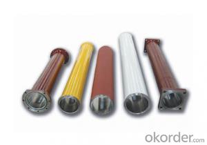
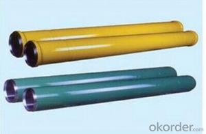


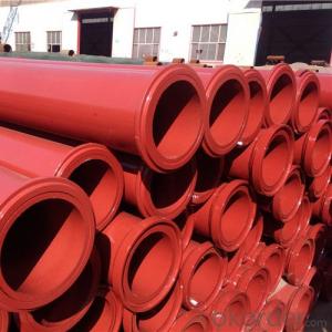
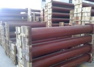
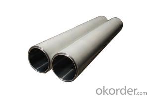
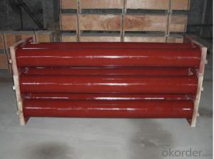
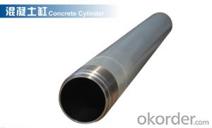
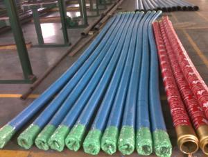
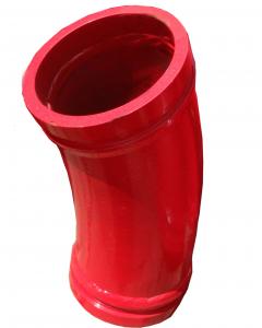
PUMPING CYLINDER(PM) I.D.:DN230 CR. THICKNESS :0.25MM-0.3MM LENGTH:2320MM
- Ref Price:
-

- Loading Port:
- Shanghai
- Payment Terms:
- TT OR LC
- Min Order Qty:
- 2 pc
- Supply Capability:
- 1000 pc/month
OKorder Service Pledge
OKorder Financial Service
You Might Also Like
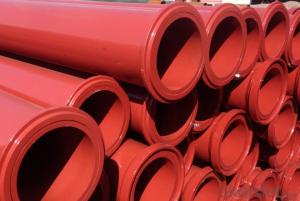
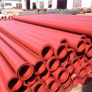
Concrete Pump Delivery Cylinder DN230*2320
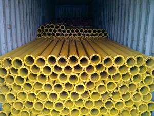
1. Capacity: 60,000~80,000cbm
2. Size: DN180, DN200, DN230..
4. Brand: PM, Sany,ZM
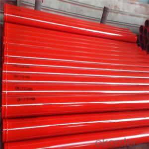
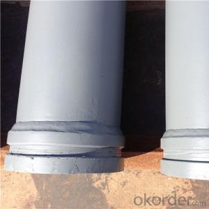
Concrete Pump Delivery Cylinder DN230*2320
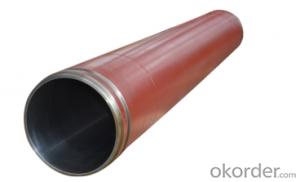
1. Material: C45
2. quenching and tempering to improve the hardness to HB241-280
3. inner wall chrome thickness is 0.25-0.30mm, hardness HV820-900.
4. Brand: SCHWING, PM, SANY, KYOKUTO, CIFA
5. Capacity: 60,000~80,000cbm
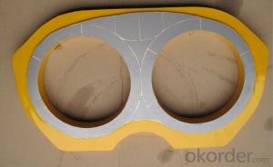
Concrete Cylinder | ||
Material | High Manganese Steel | |
Special | Coating hardness layer in the internalwall | |
Application | In concrete pump trucks | |
For Brand | Sany,Putzmeister,Schwing,,Zoomlion,CIFA etc | |
Details information | ||
Brand | Model | |
219 - DN180*1775-1600 | ||
Schwing | BP3000 | 219 - DN200*1775-1600 |
254 - DN230*2125-1800 | ||
DN230*2300mm | ||
DN230*2100mm | ||
Putzmeister | DN230*1600mm | |
DN200*1600mm | ||
DN180*2000mm | ||
40C1410 | 206-DN180*1530-1400 | |
50C1410 | 210- DN180*1545-1400 | |
60A1406 | 219- DN195*1570-1400 | |
Sany | 60C1416 | 226- DN195*1570-1400 |
60C1816 | 232- DN200*1946-1800 | |
C120/37A | 232- DN200*2162-2000 | |
C120/48 | 262- DN230*2146-2000 | |
62EA | 203-DN 180*1605-1400 | |
62G | 219-DN200*1187-1000 | |
62D | 219-DN200*1587-1400 | |
Zoomlion | 62H | 219-DN200*1787-1600 |
62CA | 219-DN200*1862-1600 | |
62M | 219-DN200*2022-1800 | |
0019931A | 219-DN200*2022-1800 | |
62L | 245-DN205*2284-2000 | |
 I.D.:DN230 CR. THICKNESS :0.25MM-0.3MM LENGTH:2320MM")
- Q: Which is the best home made concrete pump car?
- The three line is nine and Keni Le, jiubang, Linuo, etc., in addition to cheap, many of the subsequent trouble
- Q: Are there any specific guidelines for the disposal of hydraulic fluids used in concrete pump spare parts?
- Yes, there are specific guidelines for the disposal of hydraulic fluids used in concrete pump spare parts. These guidelines typically vary depending on local regulations and environmental laws. It is generally recommended to follow the manufacturer's instructions for proper disposal methods. This may involve recycling the hydraulic fluids or disposing of them at designated waste management facilities to ensure minimal environmental impact.
- Q: How often should control system sensors be calibrated or replaced?
- The calibration or replacement frequency of control system sensors varies depending on several factors, including the type of sensor, its application, environmental conditions, and the manufacturer's recommendations. Typically, it is advisable to calibrate control system sensors at least once a year. Nevertheless, certain sensors may necessitate more frequent calibration due to their sensitivity or importance in the system. For instance, sensors used in safety-critical applications or those exposed to harsh environmental conditions may require calibration every six months or even quarterly. Furthermore, it is vital to regularly monitor the performance of control system sensors to ensure accurate readings and dependable operation. This can be accomplished through routine maintenance and periodic checks. If any indications of sensor drift, inconsistency, or failure are observed during these checks, immediate calibration or replacement may be required. Additionally, the manufacturer's recommendations play a significant role in determining the intervals at which calibration or replacement should occur. Each sensor comes with its own specifications and guidelines provided by the manufacturer. It is crucial to adhere to these recommendations to maintain optimal performance and prolong the lifespan of the sensor. In conclusion, the calibration or replacement frequency of control system sensors should be determined by considering a combination of factors, including industry standards, application requirements, environmental conditions, and manufacturer's guidelines. Regular monitoring, routine maintenance, and adherence to these factors will ensure that control system sensors operate accurately and reliably.
- Q: How can one determine the correct pressure and flow rating for hydraulic components in concrete pump spare parts?
- When determining the correct pressure and flow rating for hydraulic components in concrete pump spare parts, several factors should be taken into account: 1. Review the manufacturer's specifications for the hydraulic components. These specifications should provide the recommended pressure and flow ratings for optimal performance and durability. 2. Assess the concrete pump system's specific requirements. Factors such as pump size, concrete volume and distance, and required delivery speed should be considered. These factors will help determine the necessary pressure and flow rating for the hydraulic components. 3. Ensure that the pressure and flow rating of the hydraulic components fall within the safe operating limits of the concrete pump system. Going beyond these limits can result in equipment failure, accidents, or component damage. 4. Verify the compatibility of the hydraulic components with the rest of the system. The pressure and flow rating should align with the capabilities and specifications of other components like the pump, valves, and hoses to guarantee proper functionality and performance. 5. If unsure about the appropriate pressure and flow rating, seek guidance from hydraulic system experts or the manufacturer's technical support team. They can offer advice based on their expertise and experience with similar systems. It's important to note that the pressure and flow rating of hydraulic components may vary depending on the specific model, design, and intended application. Therefore, referring to the manufacturer's guidelines and recommendations is crucial to accurately determine the correct pressure and flow rating for hydraulic components in concrete pump spare parts.
- Q: What is the function of a concrete pump remote control?
- The concrete pump remote control is a tool that enables the operation and control of a concrete pump from a distance. It grants the operator the ability to manipulate various aspects of the pump's functioning, including initiating and terminating the pumping process, adjusting the pump's speed and direction, and governing the placement and flow of the concrete. Through its capacity for remote control, it eliminates the necessity for the operator to be in close physical proximity to the pump, thereby enabling a safer and more efficient operation. Furthermore, the remote control frequently incorporates additional features, such as emergency stop buttons, diagnostics, and data logging capabilities, which further augment the functionality and dependability of the concrete pump. In summary, the concrete pump remote control serves to provide convenience, accuracy, and safety in the operation of concrete pumping equipment.
- Q: What is the function of a concrete pump control valve?
- The purpose of a concrete pump control valve is to regulate the concrete flow from the pump to the desired location. By controlling the speed and direction of the concrete, it ensures precise placement. Furthermore, the control valve aids in preventing blockages in the pumping system by enabling the operator to adjust the pressure and flow rate of the concrete. Moreover, it contributes to the safety of the operation as the operator can stop or start the concrete flow as required. In conclusion, the concrete pump control valve is essential for the efficient and effective transfer of concrete from the pump to the desired location.
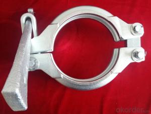
- Q: What is the function of a concrete pump hopper grate clamp?
- A concrete pump hopper grate clamp is a device used to secure the hopper grate in place on a concrete pump. The hopper grate is an essential component of the pump that acts as a filter to prevent large debris and foreign objects from entering the pump system. The clamp is designed to hold the hopper grate tightly in place, ensuring that it remains secure during the pumping process. By keeping the hopper grate in place, the clamp helps to maintain the integrity of the pump system and prevent any potential damage or blockages that could occur from the entry of unwanted materials. Overall, the function of a concrete pump hopper grate clamp is to provide a secure and reliable way to keep the hopper grate in place, allowing for smooth and efficient concrete pumping operations.
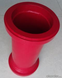
- Q: What is the purpose of a concrete pump cylinder?
- The primary aim of a concrete pump cylinder is to generate the required pressure and force for the transportation and delivery of concrete to a desired location. It serves as a vital element within a concrete pump, facilitating the smooth and productive movement of concrete throughout the pump system. The cylinder operates by utilizing hydraulic pressure to propel the concrete through the pipeline, guaranteeing a continuous and seamless flow. Its significance lies in its contribution to construction projects, enabling accurate and efficient placement of concrete in diverse settings such as buildings, bridges, and other structures. By supplying the necessary power and pressure, the concrete pump cylinder ensures effortless and labor-saving transportation of concrete over long distances, both vertically and horizontally. Ultimately, its purpose revolves around enhancing the efficiency and precision of concrete delivery, thereby saving time and effort in construction endeavors.
- Q: What is the function of a concrete pump hydraulic motor?
- The function of a concrete pump hydraulic motor is to provide the necessary power and motion to operate the pumping mechanism of the concrete pump.
- Q: How can a faulty outrigger affect the stability of the pump?
- A faulty outrigger can significantly affect the stability of a pump. The outrigger is an essential component that helps to support and balance the pump during operation. It acts as a stabilizer and prevents the pump from tipping over or vibrating excessively. If the outrigger is faulty, it may not provide the necessary support and stability required for the pump to function properly. This can lead to various stability issues. For example, the pump may become more prone to tipping over, especially if it is subjected to uneven surfaces or strong vibrations. This can be extremely dangerous, especially if the pump is dealing with hazardous or flammable materials. Additionally, a faulty outrigger can cause the pump to vibrate excessively. Vibrations can lead to increased wear and tear on the pump, resulting in premature failure of critical components. Excessive vibrations can also cause damage to the surrounding infrastructure or equipment, leading to costly repairs or even accidents. Furthermore, a faulty outrigger can affect the accuracy and efficiency of the pump's operation. If the pump is not properly stabilized, it may not be able to maintain a consistent flow rate or pressure, affecting its performance. This can result in inefficiencies, increased energy consumption, and even reduced productivity. In conclusion, a faulty outrigger can have a detrimental impact on the stability of a pump. It can increase the risk of accidents, cause excessive vibrations, and affect the pump's performance and efficiency. Regular maintenance and inspections are crucial to ensure that the outrigger and other support systems are functioning correctly to maintain the stability and reliability of the pump.
Send your message to us
PUMPING CYLINDER(PM) I.D.:DN230 CR. THICKNESS :0.25MM-0.3MM LENGTH:2320MM
- Ref Price:
-
- Loading Port:
- Shanghai
- Payment Terms:
- TT OR LC
- Min Order Qty:
- 2 pc
- Supply Capability:
- 1000 pc/month
OKorder Service Pledge
OKorder Financial Service
Similar products

Hot products
Hot Searches
Related keywords

