

Mild Steel Hot Rolled I Beam IPE In Construction Use
- Ref Price:
-

- Loading Port:
- China main port
- Payment Terms:
- TT or LC
- Min Order Qty:
- 25 m.t.
- Supply Capability:
- 10000 m.t./month
OKorder Service Pledge
OKorder Financial Service
You Might Also Like
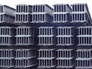
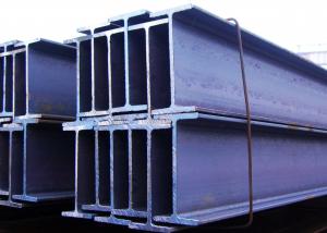
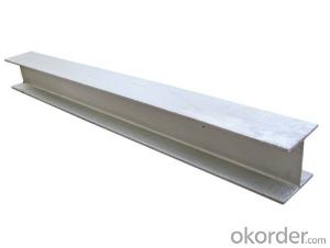
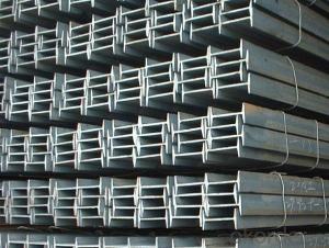
Structure of Mild Steel Hot Rolled I Beam IPE In Construction Use Description:
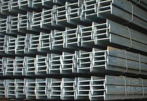
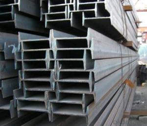
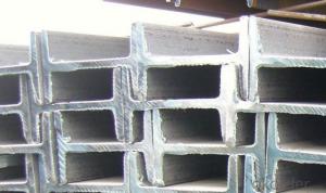
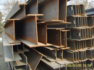
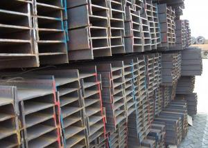
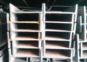
Mild steel hot rolled I beam IPE in construction use is a beam with an I-shaped cross-section. The horizontal elements of the "I" are known as flanges, while the vertical element is termed the "web". Mild steel hot rolled I beam IPE in construction use is usually made of structural steel and is used in construction and civil engineering. The mild steel hot rolled I beam IPE in construction use resists shear forces, while the flanges resist most of the bending moment experienced by the beam. Mild steel hot rolled I beam IPE in construction use theory shows that the I-shaped section is a very efficient form for carrying both bending and shears loads in the plane of the web.
2. Main Features of Mild Steel Hot Rolled I Beam IPE In Construction Use:
• Grade: Q235
• Type: Mild carbon steel
• Deflection: The stiffness of the I-beam will be chosen to minimize deformation
• Vibration: The stiffness and mass are chosen to prevent unacceptable vibrations, particularly in settings sensitive to vibrations, such as offices and libraries.
• Local yield: Caused by concentrated loads, such as at the beam's point of support.
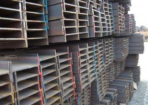
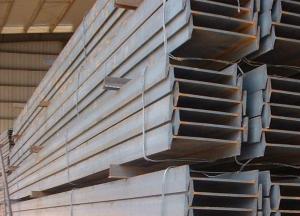
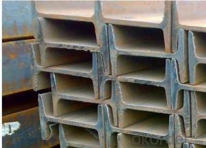
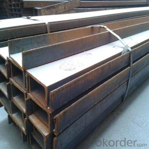
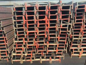
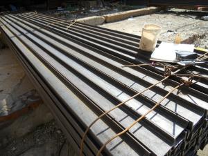
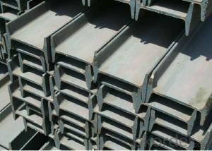
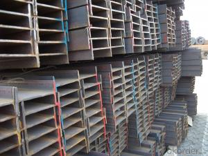
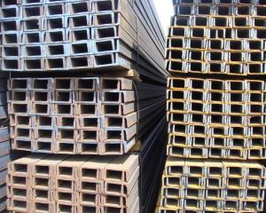
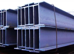
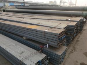
3. Mild Steel Hot Rolled I Beam IPE In Construction Use Images:


4. Mild Steel Hot Rolled I Beam IPE In Construction Use Specification:
Mechanical Properties | Grade | Steel diameter(mm) | |||
≤16 | 16~40 | 40~60 | 60~100 | ||
Yield Point Δs/MPa | Q195 | ≥195 | ≥185 | - | - |
Q235 | 235 | 225 | 215 | 205 | |
Tensile Strength | Q195 | 315~390 | |||
Q235 | 375~500 | ||||
Elongation δ5% | Q195 | ≥33 | ≥32 | - | - |
Q235 | 26 | 25 | 24 | 23 | |
5. FAQ
We have organized several common questions for our clients,may help you sincerely:
①Is this product same as W beam?
In the United States, the most commonly mentioned I-beam is the wide-flange (W) shape. These beams have flanges in which the planes are nearly parallel. Other I-beams include American Standard (designated S) shapes, in which flange surfaces are not parallel, and H-piles (designated HP), which are typically used as pile foundations. Wide-flange shapes are available in grade ASTM A992,[4] which has generally replaced the older ASTM grades A572 and A36.
②How to inspect the quality?
We have a professional inspection group which belongs to our company. We resolutely put an end to unqualified products flowing into the market. At the same time, we will provide necessary follow-up service assurance.
③Is there any advantage about this kind of product?
Steel I beam bar IPE has a reduced capacity in the transverse direction, and is also inefficient in carrying torsion, for which hollow structural sections are often preferred.
- Q: Can steel I-beams be used for solar panel supports?
- Indeed, steel I-beams possess the capability to serve as supports for solar panels. Renowned within the construction industry for their exceptional strength and durability, these structural components are frequently employed. Their remarkable load-bearing capacity renders them suitable for sustaining solar panels. Moreover, steel I-beams are effortlessly manufactured and installed, thereby offering a cost-effective alternative for solar panel mounting systems. The robustness of steel I-beams guarantees the stability and endurance of solar panel installations, even amidst harsh weather conditions.
- Q: Can steel I-beams be used for residential renovations?
- Yes, steel I-beams can be used for residential renovations. They are commonly used to provide structural support in home remodeling projects, particularly when removing load-bearing walls or creating open floor plans. Steel I-beams offer strength and durability, allowing for larger spans and minimizing the need for additional support columns or walls. However, the feasibility of using steel I-beams in residential renovations will depend on various factors such as the specific project requirements, budget limitations, and the expertise of the construction team.
- Q: What are the different types of connections used with steel I-beams?
- There are several types of connections used with steel I-beams, each serving a specific purpose and offering unique advantages. Here are some of the most common types of connections: 1. Welded connections: This is the most common method of connecting steel I-beams. It involves welding the beam flanges (horizontal sections) or web (vertical section) to other structural members or accessories. Welded connections provide excellent strength and stiffness, ensuring a secure and rigid connection. 2. Bolted connections: Bolted connections involve using bolts, nuts, and washers to connect steel I-beams. These connections are typically used when disassembly or modification may be required in the future. Bolted connections offer ease of installation and can be quickly assembled or disassembled, making them a popular choice in situations where flexibility is needed. 3. Riveted connections: Riveted connections were commonly used in the past but have been largely replaced by welded or bolted connections. They involve using hot-driven rivets to connect the steel I-beam components. Riveted connections provide good strength and durability but are more time-consuming and require skilled labor for installation. 4. Moment connections: A moment connection is a type of welded or bolted connection that allows rotational movement between the connected members. This connection is used to transfer bending moments between beams and columns, providing stability and resisting lateral forces. Moment connections are commonly used in steel frame structures and are designed to withstand large loads and significant forces. 5. Shear connections: Shear connections are used to transfer shear forces between steel I-beams. These connections are typically achieved through welding or bolting plates or angles to the beam flanges. Shear connections ensure load transfer between beams and provide stability and rigidity to the overall structure. 6. Cleat connections: Cleat connections are a type of bolted connection that involves attaching a steel plate, known as a cleat, to the flanges of the steel I-beam. This connection is commonly used in situations where the beam needs to be connected to a support or another structural member, such as in roof or floor systems. These are just some of the different types of connections used with steel I-beams. The choice of connection depends on factors such as load requirements, structural design, ease of installation, and future flexibility. Consulting with a structural engineer or a professional in the field is recommended to determine the most suitable connection for a specific application.
- Q: How do steel I-beams contribute to the overall acoustics of a building?
- Playing a significant role in the overall acoustics of a building, steel I-beams, which are commonly utilized in the construction industry, have various effects on sound transmission and reverberation within a space. A key contribution of steel I-beams to the overall acoustics is their function as sound barriers. Due to their massive and dense nature, these beams effectively hinder or absorb sound waves, preventing their passage and reducing the transmission of undesired noise. This proves particularly advantageous in spaces where noise control is essential, such as theaters, concert halls, or recording studios. Furthermore, steel I-beams can impact the reverberation time within a building. When sound waves encounter these beams, they can be partially reflected, diffused, or absorbed. The geometry and surface characteristics of the I-beams determine how sound is scattered and distributed throughout the space, thereby affecting the overall acoustics. Architects and designers can strategically position steel I-beams to manipulate the acoustics of a room, enhancing sound quality and creating a more enjoyable listening environment. The vibrational behavior of steel I-beams is another aspect to consider. When subjected to sound waves or other vibrations, these beams can resonate and generate secondary sound waves. Depending on the specific design objectives, this phenomenon can be both advantageous and detrimental to the acoustics of a building. Architects may exploit this resonance in some cases to amplify or enhance certain frequencies, thus optimizing the acoustic experience. However, excessive resonance can result in unwanted noise or vibrations, negatively impacting the overall acoustics. In conclusion, steel I-beams contribute to the overall acoustics of a building through their ability to block, absorb, reflect, and scatter sound waves. They function as sound barriers, reducing noise transmission, while also influencing the reverberation time and vibrational behavior of a space. By carefully considering the placement and design of steel I-beams, architects and designers can effectively control and enhance the acoustics, ensuring an optimal auditory experience for occupants.
- Q: What is the supply length of 30# I-beam?
- The supply length of 30# I-beam is usually 12 meters. The length of the steel bar is generally 9m and 12m; the length of the I-beam and H section steel is generally 12m; the factory length of the angle steel is generally 6 meters; the common length of the channel steel is 6 meters, /8 meters and /9 meters.
- Q: Can Steel I-Beams be used for conveyor systems?
- Yes, steel I-beams can be used for conveyor systems. I-beams provide strength, stability, and durability, making them suitable for supporting heavy loads and withstanding the demands of conveyor operations.
- Q: What is the maximum allowable deflection of No. 16 I-beam suspension 1300?
- Deflection (German Durchbiegung, French La FL Che) - bending deformation, the centroid of cross section along the vertical axis and the direction of the line displacement is called deflection, gamma said. In short, the maximum deformation of the flexural members such as beams, trusses, etc., usually refers to the vertical direction of the Y axis, which is the vertical deformation of the members.
- Q: Are steel I-beams suitable for modular construction methods?
- Yes, steel I-beams are suitable for modular construction methods. Steel I-beams are widely used in modular construction due to their strength, durability, and versatility. They can effectively support heavy loads, making them ideal for constructing modular buildings that require structural stability. The I-shape design of these beams provides excellent resistance to bending and twisting forces, ensuring the overall stability of the modular structure. Moreover, the use of steel I-beams in modular construction allows for efficient and flexible building techniques. These beams can be easily prefabricated off-site and then transported to the construction site for assembly. This streamlined process reduces construction time and costs, making modular construction methods more cost-effective and time-efficient. Additionally, steel I-beams offer design flexibility in modular construction. They can be engineered to various sizes and lengths, allowing for customized building designs and configurations. This adaptability makes it easier to meet the specific requirements and design preferences of different modular projects. Furthermore, steel I-beams are highly resistant to fire, corrosion, and pests, ensuring long-term durability and minimal maintenance. This makes them suitable for modular buildings with high-quality standards and long lifespan expectations. In summary, steel I-beams are well-suited for modular construction methods. Their strength, durability, versatility, and ease of prefabrication make them an excellent choice for modular buildings, providing structural stability, cost-effectiveness, design flexibility, and long-term durability.
- Q: What are the different types of steel I-beam connections for column support?
- There are several different types of steel I-beam connections used for column support, including bolted connections, welded connections, and moment connections.
- Q: What are the design considerations for steel I-beams in high-snow load areas?
- Considerations for designing steel I-beams in high-snow load areas primarily focus on maintaining structural integrity and load-bearing capacity. Key factors to consider include: 1. Calculating snow load: The first step is accurately determining the amount of snow the I-beams will bear. This involves considering snowfall intensity, snow density, and the structure's shape. This information is crucial for determining the correct size and spacing of the I-beams. 2. Choosing the right steel grade: Selecting a steel grade capable of withstanding heavy snow loads is crucial. Higher-grade steels with increased strength and durability are often preferred in high snow load areas. It's important to consider the potential for corrosion caused by moisture and salt exposure from snow and ice melting agents. 3. Determining beam size and spacing: The I-beams' size and spacing should be designed to adequately support the expected snow load. This requires determining the maximum bending moment, shear force, and deflection the beams will experience. Structural engineers rely on various calculations and software tools to determine the optimal size and spacing for the safe carrying of the snow load. 4. Designing connections and supports: The connections between the I-beams and other structural elements, such as columns and foundations, must be carefully designed to withstand the snow load. Adequate bracing and anchorage are essential to prevent excessive deflection and ensure stability. Additionally, proper supports and bearings must be provided to evenly distribute the load and prevent localized stress concentrations. 5. Considering clearances and roof pitch: The design should also account for the necessary clearances between the snow and the beams. Sufficient space should be provided to avoid snow accumulation that exceeds the design load. Additionally, the roof pitch, or slope, should be carefully planned to allow snow to slide off, reducing the overall load on the I-beams. 6. Implementing snow retention systems: In some cases, snow retention systems may be required to prevent sudden snow slides or excessive accumulation. These systems, such as snow guards or snow fences, aid in distributing and controlling the load on the I-beams, preventing potential damage or collapse. In conclusion, designing steel I-beams in high-snow load areas demands a comprehensive understanding of anticipated loads, structural behavior, and adherence to appropriate design codes and standards. Consulting a qualified structural engineer is crucial to ensure the safe and efficient design of these beams.
Send your message to us
Mild Steel Hot Rolled I Beam IPE In Construction Use
- Ref Price:
-
- Loading Port:
- China main port
- Payment Terms:
- TT or LC
- Min Order Qty:
- 25 m.t.
- Supply Capability:
- 10000 m.t./month
OKorder Service Pledge
OKorder Financial Service
Similar products
Hot products
Hot Searches
Related keywords

