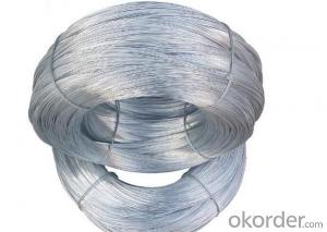
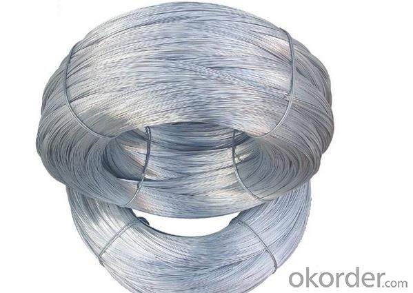
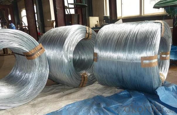
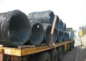
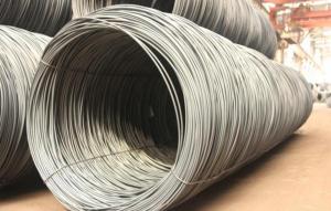
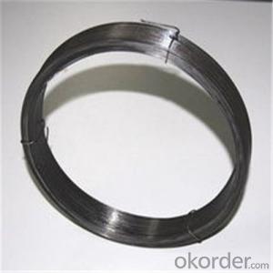
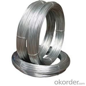
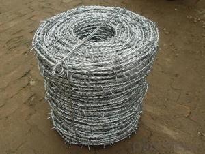
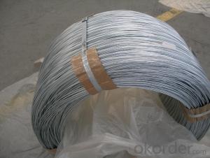
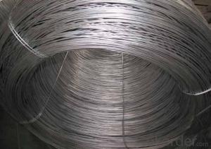
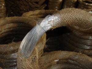
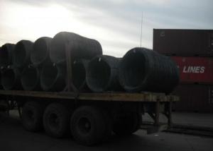
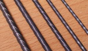
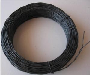
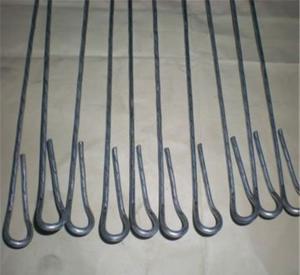
High Quality Galvanized Iron Wire Roll
- Loading Port:
- China Main Port
- Payment Terms:
- TT OR LC
- Min Order Qty:
- -
- Supply Capability:
- -
OKorder Service Pledge
Quality Product, Order Online Tracking, Timely Delivery
OKorder Financial Service
Credit Rating, Credit Services, Credit Purchasing
You Might Also Like
Quick Details
| Place of Origin: | Standard of Zinc Coating: | Model Number: | |||||||
| Surface Treatment: | Galvanized Technique: | Type: | |||||||
| Function: | Wire Gauge: | Standard: | |||||||
| Material: | Elongation: | Package: | |||||||
| Zinc Coating: | Application: | Used in wire mesh, artware , metal hose , binding wire | |||||||
Tensile Strength Range
Size (mm) | Tensile Strength (mpa) |
0.15-1.60 | 290-550 |
0.65-1.60 | 400-550 |
1.61-6.00 | 400-1200 |
- Q: my speaker makes a fuzzy or static noise while the scene has high or low sound. I cut my wire in half because I bought a subwoofer and we didn't get the wires with it. So I cut it. After all I didn't need the wire for the subwoofer. Could my speakers make such noises because of cutting a wire?
- Shortening your speaker wire will not cause this problem. In fact, shortening your speaker wires should give you less static since there is less resistance. Most than likely, it's not your speakers causing the static sound, but your amplifier or receiver. You may be looking for a new one soon.
- Q: I have a set of pilot wi-200 strobe lights and they have three wires and i want to hook them up to a optx headlight strobe control module the wires are gray white and black can you tell me where to hook them
- I wouldn't try it. The gray, white, and black wires are the high voltage strobe wires. The control module changes the patterns before the voltage is increased. There is nothing you can do here.
- Q: i need to know which wire is which in a 1999 dodge stratus for the cars stereo
- its usually pretty easy if you look online just goodle it red is usually constant power yellow is usually switched power black is usually ground blue is usually for the rem wire the rest are speaker wires or are not used good luck
- Q: I have this sony x plod headunit that i want to install.unfortunetely i do not know the wiring on it. i could find out as i go along which wires go to which speakers... but which two wires are the POWER wires?so i attached pictures but the basic layout is on the left side there are 4 sets of two wires (im assuming they pair up vertically)on the right side there is a long black wire with a metal hook on the end.
- Please do not waste your time on that stereo. It has ridiculously poor sound reproduction. Sony makes some of THE WORST stereos on the market.
- Q: How do you wire an electrical outlet and light switch in a bathroom? Box is existing, wires existing.
- Make sure you get an GFCI outlet ..
- Q: I recently bought a set of DT Moto emergency lights for my pickup and after installing them i found when i went to wire them to my battery the wire was too short. I didn't install the grille lights just the visor. Could i cut wires from the grille set and wire them to extend the visor light wire?
- I'm looking online to find out what DT Moto lights are. Ok, I see what they are. I didn't know the brand name. LED lights in general are not high current, so they probably use lamp cord. I want to explain something to you about polarity. Electronic circuits are sensitive to the polarity of the DC electricity. The positive (+) and the negative (-) connections must be observed. So many people have absolutely no clue about this. There are just two wires. But if you extend them, you have a 50-50 chance of wiring correctly or incorrectly. There is only one allowable way. If wrong, it WON'T work, and probably will blow up the circuitry. So connection to battery or cigarette lighter plug is extremely important not to reverse the polarity. If just the LED lights got reversed, they wouldn't light, but they wouldn't be injured. Just reverse the wiring. But to the 12 volt source, polarity can't be wrong. Not for an instant. If you look closely at the insulation, you will see that one wire has smooth insulation, and one wire either has milti-ribbed insulation, or a single rib down the side. If you extend wiring, make sure to connect smooth to smooth and ribbed to ribbed. Wires should be soldered with electronic solder and the joints covered with heat shrink tubing. No crimped barrel connectors, or twisted bare wires with tape, or house wiring wire nuts. These methods all beg for failure. I don't know about robbing wire from one place and connecting to another. Is the one wire actually too long? You'll never need it? I guess you could take it. But me personally, I'd go get some wire from a lamp store. Match the wire conductor gauge (size), not the insulation size. Most lamp cord is 18 gauge. Some is 16 gauge. You can get 14 gauge or even 12 gauge. Thicker is a smaller number. Places that install car audio systems often have/sell thicker lamp cord. Have I told you enough?
- Q: I currently have a ceiling fan wired to a dimmer wall switch that controls the fan and the light, not good I know. I would like to set up the dimmer switch where it controls the light only and then i can use the fan pull switch for the fan. but i am not sure how to wire this with my current wires. In the wall box where the dimmer switch is I have two sets of wires coming from two different locations. one set has a black, red, white, and green. the other location has black, white and copper. currently the green and copper are connected and capped, the two whites are connected together and capped, two blacks are and connected to the black wire coming from the dimmer and the red is connected to the other black wire from the dimmer. how would I wire the dimmer switch to only control the light and not the fan? I want to make sure i do this safely.any assistance is greatly appreciated.
- Ok, leave the copper and green wires alone as well as the white wires. Now the red and black coming from the same set should be your fan/light switch legs with red being light and black for fan itself. You may have to go into the fan ceiling box itself as it sounds the fan and light kit are connected to red wire in ceiling box especiallly if dimmer switch is controlling both. The other blacks are power legs. If both wires from fan/light are tied in with red wire, seperate them and connect the blue wire from light kit to red and cap off. With switch off, connect black wire from fan to those black wires that are capped off in box. If this isnt right connections, contact me via my email address on profile
- Q: want to get ready to solderis the fuzzy stuff the wire? or the shiny (positive green and negative red color) the wire? sorry i know its a noob questionlet me knowthanks
- wire is metal and metal is orange or silver . The fussy stuff is string
- Q: Okay so my question is how would I wire these in a ported box with 2 terminals on each side of the box? Also, is the quot;Bridged Wirefeatured in the diagram negative speaker wire? Thanks.
- Bridging isn't something you do with the subs wiring. It's the way you wire them on the terminals. Each amp's manual should tell you which terminals are the bridgeable ones. That's a mono amp. There's not much you can do there with bridging etc..Try looking for a 2 channel bridgeable amp and then worry about wiring the subs. Not sure why you would want two terminals on both sides of the box anyway.
- Q: ok...all the wires in my quot;atticare encased in this silver metal casing....when i opened a bathroom wall...the wires were also like that.....at the fuse box...they all leave like that........sooooo, can i assume all my wires are encased like that? does that make them pretty safe from rodents chewing? (yup-been watching Billy the Exterminator) why were they done like that? tx for any info....
- hi kate in Engand we call it trunking but ime pretty sure its the same stuff, we also cal lit conguate but ime not sure the spell on that is right anyhow we have it white in the uk not sure what your question is but i can only say that its used mainly for protection against animals and more often than not...people hope ive helped danx
Send your message to us
High Quality Galvanized Iron Wire Roll
- Loading Port:
- China Main Port
- Payment Terms:
- TT OR LC
- Min Order Qty:
- -
- Supply Capability:
- -
OKorder Service Pledge
Quality Product, Order Online Tracking, Timely Delivery
OKorder Financial Service
Credit Rating, Credit Services, Credit Purchasing
Similar products
Hot products
Hot Searches
Related keywords
