


High Quality Galvanized Hexagonal Wire Mesh
- Ref Price:
-

- Loading Port:
- China Main Port
- Payment Terms:
- TT OR LC
- Min Order Qty:
- -
- Supply Capability:
- -
OKorder Service Pledge
OKorder Financial Service
You Might Also Like


Quick Details
| Place of Origin: | Wire Gauge: | Model Number: | |||
| Type: | Application: | Hole Shape: | |||
| Aperture: | Material: |
Packaging & Delivery
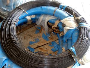
| Packaging Detail: | 1.With plastic weaving bags outside 2.With wooden pallet cloth 3.According to customer's request |
| Delivery Detail: | 30 days after receive the deposit |
Specifications
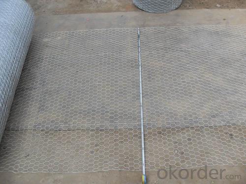
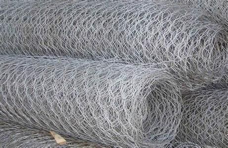
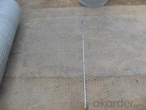
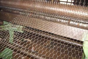
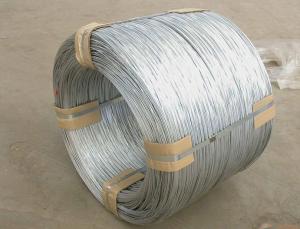
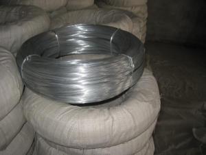
hexagonal wire mesh
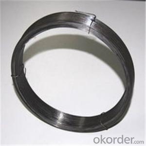
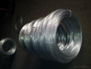
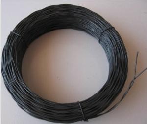
1>material: galvanized or plastic-coated wire
2>Mesh: 3/8" -4"
3>hole shape:hexagon
4>Length: 5-30m
Hexagonal wire mesh
Hexagonal wire mesh is also known by the name of chicken mesh.
Wire materials: Hexagonal wire mesh is manufactured in galvanized iron or PVC coated wire.
Application: Hexagonal wire mesh with its good corrosion resistance and oxidation resistance, serves well as strengthening, protection and temperature keeping materials in the form of mesh container, stone cage, isolation wall, boiler cover or poultry fence in construction, chemical, breeding, garden and food processing industries.
Hex netting welded mesh(Galvanized before wearing) | ||||||
Spacing(mm) | Dia | Width(mm) | Length | |||
41 | 1.40mm | 450/600/1066 | 50m | |||
31 | 18g/19g | 900/1050/1200 | 50m | |||
50 | 18g/19g | 900/1050/1200 | 50m | |||
Hex netting welded mesh(Galvanized after wearing) | ||||||
Spacing (mm) | Diameter | Width (mm) | Length | |||
13 | 0.7mm/0.9mm/1.0mm | 900/2000 | 5m/10m/50m | |||
13 | 18g/19g/20g/22g/23g | 600/900/1200/1800 | 5m/10m/25m/50m | |||
19 | 0.7mm/0.9mm/1.0mm | 900/2000 | 5m/10m/50m | |||
25 | 0.7mm/0.9mm/1.0mm | 900/2000 | 5m/10m/50m | |||
25 | 18g/19g/20g/22g/23g | 600/900/1200/1800 | 5m/10m/25m/50m | |||
31 | 18g/19g/20g/22g/23g | 600/900/1200/1800 | 5m/10m/25m/50m | |||
50 | 0.7mm/0.9mm/1.0mm | 900/2000 | 5m/10m/50m | |||
50 | 18g/19g/20g/22g/23g | 600/900/1200/1800 | 5m/10m/25m/50m | |||
75 | 0.7mm/0.9mm/1.0mm | 900/2000 | 5m/10m/50m | |||
- Q: I am doing wiring in my shed on preexisting light fixtures and outlets. the wiring that was disconnect from that carried the electricity to it. What I am trying to do is have all the light fixtures work of an extension cord. I have another extension wire connected to that with the +, - and 0 showing. The fixtures have 3 wires coming out of them what I think to be the power in, power out, and switch. On the fixture on the end I connected my extension cord thing and it work, BUT only that one. The rest of the fixtures did not work, I do see anything wrong. What I thought was that I was connecting to the switch wire so I changed it and it just buzzed with blue light. What is going on?
- the rest of your light fixtures maybe wired through a switch. you would have to hook your extension cord to the switch but you also need to connect the common neutrals and grounds to the cord as well.
- Q: the 2 wires that is connected from the key hole is cut .. how to fix or replace?
- If there enough wire left on each side of the cut, say 1, then you could bear about 1/4 of the wire on each side and solder the wires back together making sure you are soldering the same wires together and wrap each soldered connection in electrical tape so they are not able to touch each other. Then a final wrap of tape around them both. If you are not up to soldering you could go to an auto parts shop and get a crimp connector to do the job, again bearing of wire is needed to get a contact through the cut area. If the cut is closer to the switch then there is no option but to replace the switch.....
- Q: I'm faced with a dilemma...I'm wiring my basement right now and all is fine, except for my living room. I want to have a 3-way switch setup, but with four light fixtures. I've already ran 3+ground wires in this order...Breaker box - Switch A - Fixture 1 - Fix. 2 - Fix. 3 - Fix. 4 - Switch B. I have done regular 3-way switches in the past, without much trouble, but I have no idea how to wire this, so well-explained instructions would be perfect.Thanks so much!
- i hope i can give you good instructions. you have 2 switches you want to operate the lights. first. pull a feed or wire that will be hot probarly from your panel box to the easiest switch to get to. this wire should have 1 black 1 white and one bare copper or green. second pull a three wire from one switch to the other. this wire should have one black one white one bare copper or green and one red wire in it. now there are 2 different ways to go from here. one way. pull a wire from the switch opposite of the switch with the feed in it. this wire would be called a 2 wire it should have 1 black 1 white 1 bare copper or green, to the first light you want to operate. then you can pull a 2 wire from that light to any other light you want to operate from the switches. you do not need to pull any more wires from the lights to the switches. in the first switch with the feed take the white wire from the feed and tie it to the white wire from the 3 wire going to the other switch. take your grounds and tie them together. leave a wire from your grounds so you can tie it to the switch. put you white wires back into the box. you should have 2 blacks 1 red and 1 ground wire sticking out. when you install your switch a three-way switch has 4 screws on it. the ground goes to the green screw. now you have one black screw and 2 gold screws. the black wire from your feed wire ties to the black screw. the red and black wire from your 3 wire ties to the gold screw. one wire to on screw the other wire to the other screw. does not matter which. the opposite switch hooks up the same. the 2 white tie together and go into box. the grounds tie together and then tie to the green screw. the black wire going to your lights ties to the black screw and the red and black wires from the 3 wire go to the gold screws. remember if you are using 14 wire you can only put 12 amps on it that would be about 1400 watts. 12 wire you can put 16 amps on it which is 1900 watts.
- Q: the charger has three wires to put a male plug on and they are black white and green and they look like 12 gauge wires
- wire colors are green is ground the black and white wires are you load wires look at you 240 volt plug and determine which terminal is the ground this one is where the green wire goes the black and white wire go to other two terminals this should do it
- Q: I have a 1988 ford econoline, and I'm upgrading my radio. I need a straight up answer, I need to know what the colors for each wire stands for, function wise.
- The okorder /
- Q: I need to get to the audio wiring
- you cannot simply go with matching the colors factory radios have extra wires that are not needed with an aftermarket install most of the time (wires that control the dimmer on the radio, speed sensitive volume) you will need three power wires (constant, ignition, and ground), plus your speaker wires use a test light to test your wires, usually at the radio the yellow wire is your constant, the red is your ignition, and black is always ground to find your constant use the test light, it will be hot at all times so that your radio can remember the time, and your settings- next you need your ignition, it is only hot when the key is on or in the accessory position, to tell the radio when to come on- the ground is self explanatory to find which wires go to what speakers all you need is a 9v battery, put the positive end to a wire and test all of the other wires to the negative side and you will hear a crackling noise from a speaker when you have the right combination
- Q: have 0 gauge power wire, but don't have a ground wire! can I use the power wire as a ground wire if I cut a piece off?
- 0 gauge? you probably have 14 awg, and yes, you can cut off a piece and use it as the ground strap, but you would be better off to use an actual ground wire, because later on if someone goes to work on that outlet they could miswire the new one. EDIT whoops, just saw the category, i saw this question on the main page, i was thinking home AC...not car audio, my bad.
- Q: Is there anything else I could use to solder things without buying whole long spool of soldering wires? I mean like the wire inside the TV antenna cable from 99c store or nails and etc. ? Something I could use single time.
- If you could get a small spool of solder and flux from Menard, for plumbing that also works.
- Q: the wires that are in most electric appliances
- Hot, neutral, and ground. black wire is hot (right side of outlet) --this is the one that can shock you. white wire is neutral( left side of outlet) green wire is ground(bottom side of outlet) when wiring an outlet black goes to gold screw, white goes to silver screw, and green goes to the ground(bottom) screw. remember black-gold white -silver green to ground the world around
- Q: Two long straight parallel wires are 12 cm apart. Wire A carries 2.5 A current. Wire B's current is 3.7 A in t?Two long straight parallel wires are 12 cm apart. Wire A carries 2.5 A current. Wire B's current is 3.7 A in the same direction.1) Determine the magnetic field magnitude due to wire A at the position of wire BB = ? T2) Determine the magnetic field due to wire B at the position of wire A.B = ? T3) Are these two magnetic fields equal and opposite? Why or why not?4) Determine the force on wire A due to wire B, and the force on wire B due to wire A.
- (1) wire-A B = (uo)(I) / (2pi * r) B = (1.26E-6)(2.5) / (2pi * 0.12) B = 4.17E-6
Send your message to us
High Quality Galvanized Hexagonal Wire Mesh
- Ref Price:
-
- Loading Port:
- China Main Port
- Payment Terms:
- TT OR LC
- Min Order Qty:
- -
- Supply Capability:
- -
OKorder Service Pledge
OKorder Financial Service
Similar products


Hot products

Hot Searches

