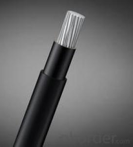
F 46 insulated special rubber
- Loading Port:
- China Main Port
- Payment Terms:
- TT OR LC
- Min Order Qty:
- -
- Supply Capability:
- 2000km m/month
OKorder Service Pledge
OKorder Financial Service
You Might Also Like
Quick Details
Place of Origin:Jiangsu, China (Mainland)
Model Number:10 conductor
Conductor Material:Copper
Insulation Material:F46
Jacket:Rubber
Number of Conductors:10
Application:oilfield, well logging, oil exploration
Packaging & Delivery
| Packaging Details: | Each Pieces Packed in High Quality Plastic Pouch. Then all Packed Products in One Master Export Box. |
|---|---|
| Delivery Detail: | 30 days after payment |
Specifications
rubber cable
a. Quick delivery
b. Competitive price with high quality
c. Free samples
d. Expert in cable and wire
10-core fluoroplastic F46 insulated special rubber protected electrode cable-20.06
1. Product Standard
The product is manufactured according to the standard of SY/T6600-2004.
2. Application
This special 10 core rebber electrode cable is for oilfield logging and is suitable for bearing load connection between oilfield downhole testing instrument and transmission of signal cable. Inside the core place setting load bearing steel strand and outside the bearing load of steel strand setting rubber sheath which can withstand oil, acid, alkali. There are 10 group copper core with fluoroplastics insulation outside, special rubber sheath outside each insulation can withstand oil, acid, alkali. Special rubber sheath outside protect this cable from oil, acid, alkali and make it work in oil, acid, alkali environment for a long time.
3. Operating Characteristics
a.The lowest temperature that cable could work should not be lower than-30°C.
b.Max temperature is 232°C for short period (2h maximum duration each time).
c.Minimum bending radius is 30 times of cable diameter.
CONSTRUCTION DESCRIPTION:
Copper Construction: | 7×0.0126’’ | 7×0.32mm |
Plastic Type: | F46 |
|
Insulation Thickness: | 0.0724’’ | 1.84 mm |
The Rubber Protecting: | 0.1338’’ | 2.95 mm |
CABLE CHARACTERISTICS:
PHYSICAL:
Cable Diameter: | 0.811’’±0.02’’ | (20.60 mm ±0.50 mm) |
Cable Weight In Air: | 457 lbs/Kft | 680 Kg/Km |
Temperature Rating : | 450 °F | 232 °C |
MECHANICAL:
Cable Breaking Strength: | 11000 lbs | 49 KN |
Minimum Sheave Diameter: | 20’’ | 500 mm |
ELECTRICAL:
Voltage Rating: | 1000 VDC | 1000 VDC |
Insulation Resistance: | 50000 MΩ·Kft | 15000 MΩ·Km |
DC Resistance @ 20°C | 11 Ω/Kft | 36 Ω/Km |
Cap Typical @ 1 KHz | 40 Pf/ft | 131 Pf/m |
TIP: We can produce electrode cable of which breaking strength is greater than the same size over 60KN according to our customer’s requirements.
- Q: do speakers function better with thick or thin wires??
- The wiring in your car audio system is very important. The higher the gauge of wire you choose to use the less resistance will be placed on the amplifier or head unit (which have internal amplifiers). This means more power to the speakers and ultimately more quality sound. It depends on the wattage of the system to determine the appropriate gauge of wire but as a rule the bigger the better. I would recommend getting a good quality speaker wire. Good speaker wires use the most conductive metals for the wire material, such as copper. They feature thick jackets that wont wear through from rubbing and vibrations. Choose a good 16-18 gauge wire from a company like Streetwires. Dont cheap out on your speaker wire its an important part of your installation.
- Q: DO i TWIST THE WHITE AND RED SMALL WIRES TOGETHER UNDER THE WIRE NUTS ON AC WIRING TO THE CONDENSER?
- The wires you describe control the relay that starts the AC unit. The main power wires are heavy duty (black and red if this is a 220 volt unit). The light guage wires are low voltage AC and connect to the thermostat. DO NOT joint the red and white wires. There will be a terminal for the red wire. You will have to find out which one it is. Try to get the wiring diagram for your unit from the Internet or call a service professional.
- Q: My renter took apart a timer that was hooked to a ceiling fan because the timer was clicking loudly.Now, I just want to simply install a normal on/off switch in it's place. There are two sets of wires coming into the box. One set has a red,white, and black wire coming from it. The other set has just a white and black wire coming into the box. I'm sure this is relatively simple for someone who has wiring expertise. How do I wire a normal light switch to these wires?!?!
- The set of black and white wires are coming from your breaker box (supply). The Black, white and red wires are leading to your ceiling fan (demand). This next part depends on how your fan is wired up. You will want to check first. USUALLY, the red wire controls the fan only, while the black wire supplies power to the light kit, but it could be reversed. This is the part that you want to check. The red wire may also be capped off in the ceiling box and only exists if the user wants separate fan/light control in the future. Assuming that the red wire is capped off: 1.) Turn off the breaker supplying the circuit you are working on. 2.) Use a wire nut to twist the white wires together. 3.) Use a second wire nut to cap off the red wire. 4.) Wrap the black [supply] wire clockwise around the bottom screw on your new switch and tighten.. 5.) Wrap the black [demand] wire clockwise around the top screw on your new switch and tighten. 6.) Attach the new switch to the wall box while carefully tucking the wires in behind the switch. 7.) Install cover plate. 8.) Restore power to the circuit. It IS possible that the person who installed the ceiling fan used the red wire as the hot instead of the black. If this is the case, you can either rewire the ceiling fan's box accordingly (disconnecting the red wire and using the black instead) or substituting red instead of black in the instructions above. The red wire would then connect to the top screw terminal of your switch. If the red is connected to the light kit (if applicable) and the black is connected to the motor (or vise versa), disconnect the light kit and wire it along with the motor.
- Q: EL wire, or electroluminescent wire, is a wire which... well glows pretty colors lol. I want to buy some to make a costume, but I have some questions. I have a feeling that it will degrade over time, but how long will it take? Or do they start to degrade immeidately like glow sticks? What is it that causes them to glow, a chemical reaction or something else?
- Electroluminescent okorder ) have wire that lasts far longer. You can expect the shelf life of these wires to be about 4-6 years. At that time, the wire just doesn't stop working, it slowly breaks down the phosphor particles, and the wire will get dimmer over time. The expected working life of EL Wire is about 4-6,000 hours which beats your average glow stick by about 5,992 hours...
- Q: Wire 1 and wire 2 are made from the same metal. Wire 2 has a larger diameter than wire 1. The electric field strengths E1 and E2 are equal. A) Compare the values of the two current densities. Is J1 greater than, less, or equal to J2?B) Compare the values of the currents I1 and I2. Is I1 greater then, less or equal to I2?
- The current will be more dense in the smaller wire. The value of the current is inversely proportional to the resistiance of the wire. Resistance = resistivity * length / Area since the wires are of identical material and length, the only thing left to vary is the cross-sectional area. Area is proportional to the square of the radius (diameter), so the current will be proportional to the square of the diameter. I2 is proportional to I1^2 I2 is larger than I1 .
- Q: What's the best kind of wire to use that can stand being kilned?
- that really depends what you want to do and how high you are going to fire. Generally nichrome 80/20 wire should be OK until cone 9. Then there is Kanthal which will withstand even higher temperatures but is more expensive than nichrome. You could get either probably in electronics supply houses. If you do lowfire, maybe up to cone 06 or lower steel will probably be OK. The surface of the steel will oxidise and so get clearly thinner, keep that in mind. Generally your wire and the clay should not be in direct contact because they have different thermal expansion coefficients. Depends how rigid your wire is if it will lead to major damage to your piece. But if you wrap your wire with paper before you put clay around it it is probably OK as long as you don't enclose the entire thing with clay into a hollow space. But it also depends on what exactly you are trying to do, e.g. what kind of clay you are using. Mostly people use wire with clay for making beads. If that's what you are doing you can also look up bead making techniques.
- Q: so there are 3 different wires coming into the switch. 1 black wire and 2 white wires going to the attic fan (i assume one for high and one for low). the power seems to be coming from the black wire which has inside of it, one white wire (neutral) one black wire (hot) and one bare wire (ground).. the same for the 2 white wires. the switch goes up (^) for high and down (v) for low and has 3 places to attach the wires to. the top, the bottom and the middle.. can someone tell me how to wire this damn thing?
- I think you are describing NM cables(Romex). What you have is: 1 black romex with a hot(black) a neutral(white) and a bare ground. and 2 white romexs with a black, white, bare each. right so far? What you probably have is the hot and neutral going to the switch j-box (black romex) and the 2 white romexs go from the switch to the fan j-box. I think I need more info. Do you have a test meter? Are you sure the black romex is the Hot and Neutral? When the wires are disconnected are there other things that don't have power to them? Did you undo the neutral splice? If you could send this info I think I can walk you thru it.
- Q: I have 1971 slide in truck camper with 5 way pin wiring wires are red, white ,yellow, black,green.need to know what wire's do what...thanks
- The wires are as follows: 1 = Trailer (battery 12+) wire (for trailer break-away battery) 2. white= ground 3.Green= right turn 4.yellow=left turn 5.Brown ( should not be black) is the tail lamp circuit ADDED: Ground on trailers are always white! And there is NO Black wire on a trailer harness! (if there is you will need to trace it out because someone put the wrong color wire in there!
- Q: so im doing a custom buggy and i need so different colored wire im looking for a place to get lots of different colored wire for cheap
- This Site Might Help You. RE: i needed many different colored electrical wire for cheap? so im doing a custom buggy and i need so different colored wire im looking for a place to get lots of different colored wire for cheap
- Q: A vertical straight wire carrying an upward 14.2 A current exerts an attractive force per unit length of 7.80E-4 N/m on a second parallel wire 7.60 cm away. What is the magnitude of the current that flows in the second wire?
- For a current I1 = 14.2 Amperes and radial separation between wires r =0.076 m, the magnetic field at wire 2 is B =0.000037368 Tesla If current I2 = 21 Amperes then the force per meter is F/ΔL =0.000784 Newtons/m hyperphysics.phy-astr.gsu.edu/hba... Goodbye
Send your message to us
F 46 insulated special rubber
- Loading Port:
- China Main Port
- Payment Terms:
- TT OR LC
- Min Order Qty:
- -
- Supply Capability:
- 2000km m/month
OKorder Service Pledge
OKorder Financial Service
Similar products
Hot products
Hot Searches
Related keywords
