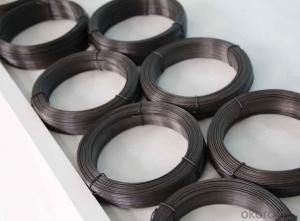
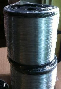
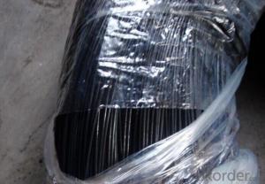
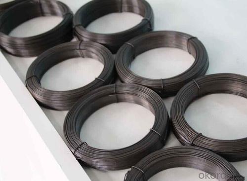
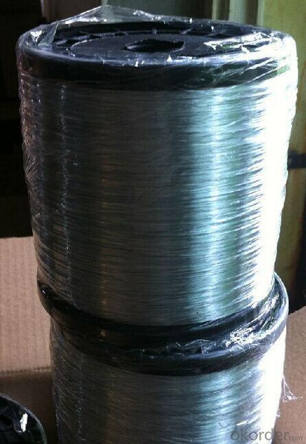
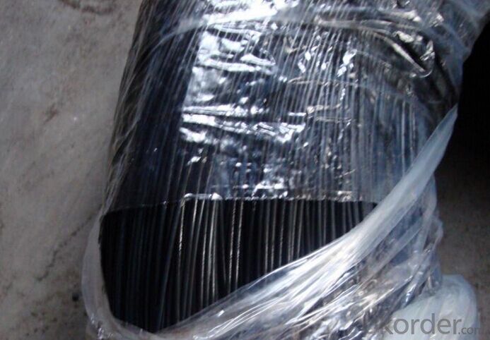
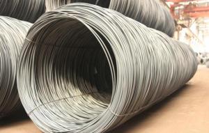
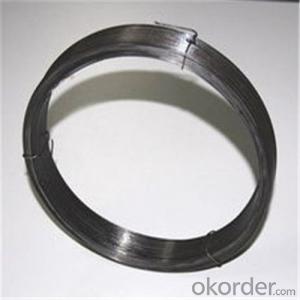
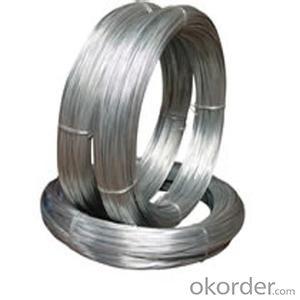
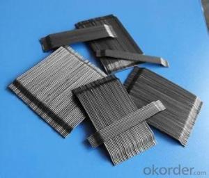
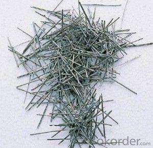
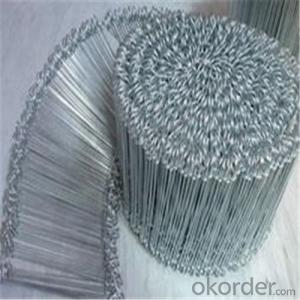
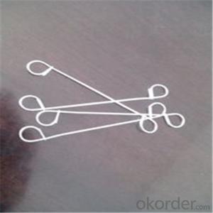
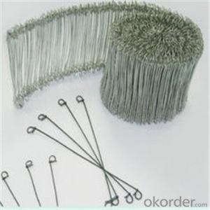
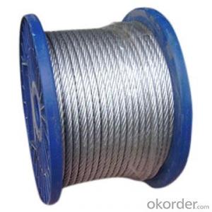
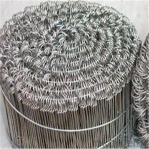
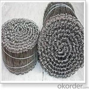
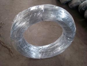
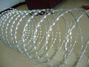
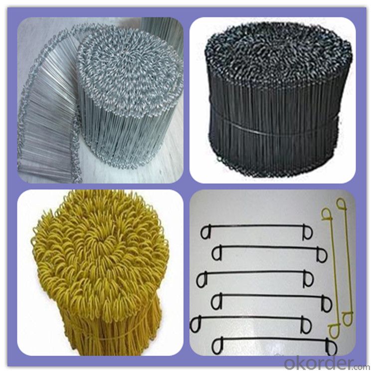
Double Loop Tie Wire From China Supplier High Quality
- Loading Port:
- Tianjin
- Payment Terms:
- TT OR LC
- Min Order Qty:
- 5 m.t.
- Supply Capability:
- 50000 m.t./month
OKorder Service Pledge
OKorder Financial Service
You Might Also Like
Specification
Product description
1. Wire style:
Electro Galvanized Iron Wire
Hot Dipped Galvanized Iron Wire
2. Use:
Mainly used in communication equipment, medical equipment and weaving nets, brushes, cables, filters, high pressure pipe, construction, handicrafts and other industries.
we can be made according to customers specific requirements
3.Features of Galvanized Wire:
Material: low carbon steel wire
Tensile Strength: 400--580Mpa
Standard wire gauge for electro galvanized iron wire: From 8# to 16#
Hot-DIP galvanized iron wire standard wire gauge: From 8# to 24#
We has devoting ourselves to producing and trading for 10 years,eatablishing a good relationship with the company of US,Canada,Mid easten and so on.
| Product name | high quality double loop tie wire from china supplier |
| Length | As your request |
| Material | Q195,Q235 |
| Coating | As your demand |
| Weight | 1-800kg/coil |
| Production QTY: | 1000tons/month |
| MOQ: | No |
| Delivery time: | 20days after payment |
| Payment terms: | T/T,L/C |
| Application: | Binding Wire |
| Remarks | No rust |
| product size: | (other size as your demands) | ||
| Wire Gauge | SWG in mm | BWG in mm | In Metric System mm |
| 8# | 4.06 | 4.19 | 4 |
| 9# | 3.66 | 3.76 | - |
| 10# | 3.25 | 3.4 | 3.5 |
| 11# | 2.95 | 3.05 | 3 |
| 12# | 2.64 | 2.77 | 2.8 |
| 13# | 2.34 | 2.41 | 2.5 |
| 14# | 2.03 | 2.11 | - |
| 15# | 1.83 | 1.83 | 1.8 |
| 16# | 1.63 | 1.65 | 1.65 |
| 17# | 1.42 | 1.47 | 1.4 |
| 18# | 1.22 | 1.25 | 1.2 |
| 19# | 1.02 | 1.07 | 1 |
| 20# | 0.91 | 0.89 | 0.9 |
| 21# | 0.81 | 0.813 | 0.8 |
| 22# | 0.71 | 0.711 | 0.7 |
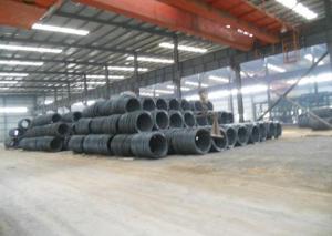
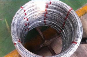
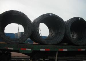
Factory photos
- Q: When wiring my subs from a positive to negative coil, do I use positive or negative speaker wire?
- Speaker wire is speaker wire. There's no difference between positive and negative wire except the markings on the jacket. If you're talking about the bridge wire when wiring a dual voice coil subwoofer in series, just use any piece of wire that's the same gauge as the wires between the other subwoofer terminals and the box terminals.
- Q: I recently re-wired my house with 4 wire telephone wire. They all meet in the attic. How do I wire them together and is there some kind of junction plate I can use? Additionally, I did also wire my house with Cat6 wire, but would like to keep it strictly for Internet.
- (links just for reference, from search engine results)
- Q: Which of the following wires would tend to have the least amount of electrical resistance? a) long b) fiberglass c) hot d) thick
- thick wires have less resistance
- Q: my internet wont pick up my wireless adapter thing now, because the internet box was reseted. How can I change it to wired?
- well basically for wired xbox live setup you need 4 things 1. xbox 360 2. internet connection ( like a bt home hub box or any form of internet box) 3. An xbox 360 4.An ethernet cable which is a two sided wire. ok so put the wire in the back of the xbox in the socket right below where the wired cable would fit. now with the other side of that cable plug it into the back of your internet hub box. Thats all there is to it really then the setting up xbox live is all on the dashboard
- Q: While updating the parents basement we needed to replace a very very old 3 way switch. However, the wiring to the Fluorescents seems extreme to me. Here is how i can describle the layout. Panel - junction box - double splice (one to light fixture and one to threeway switch below it)-. From that threeway switch 12-3 wiring to upstairs landing with other threeway switch resides. How should I make my connections to switches? If the other swtiches were not so old I would just copy them.
- A hot wire from the panel to the first three way switch on the common screw. Two runner wires between the two switches on the other two screws. A wire from the common screw on the second switch to the hot wire on the light fixtures. A neutral wire to the light fixtures from the panel. Look at Bert's pictures.
- Q: I like bending paperclips to make things, does anyone know where you could buy spools of the wire paperclips are made out of.(any type of wire that is the same size and material will work)
- For the best answers, search on this site https://shorturl.im/axqI3 No, I am afraid you can't ... you need a special alloy, not paper clips, which are mild steel.
- Q: How can it be possible to create a high voltage and have a small gauge wire? Example: 3gj or 3000mw in a small wire (just an example)
- Voltage don't matter. It's the amps that will kill the wire. Just have really high voltage and low current and you can have lots of power going through smaller gauge wires. That's how it's done with overhead power lines.
- Q: what are the ground and power wires for a walmart replacement cigarette lighter?
- In answer to your question, there is no difference in the wires because a lighter element isn't polarized, in other words, hook either wire to positive, and the other to ground. That's why both wires are black.
- Q: Their is a Shortage in the wire inside the actuall headphones, I was wondering if I could purchase a beats studio wire to rewire them.
- Any wire about the same size as the original wire will work. Only if a special connector is involved would there be any reason to replace the wiring with a manufacturer-supplied part.
- Q: Us the French wire hook earrings gold? 14kt gold?!?
- French wire earrings are a style of earrings for pierced ears. They have a long hook shape. They can come in gold or silver or any metal. The style isn't an indication of its metal content. If they are 14k gold, they will need to be stamped as such and you should buy them from a reputable jeweller. Online buying can be a problem, they are people who fake the gold markings (especially goods from Asian countries) and you might think you are getting real gold, but you aren't. Also, sometimes only the wire hook part is gold, the attachment or dangle might be an alloy metal and not gold at all.
Send your message to us
Double Loop Tie Wire From China Supplier High Quality
- Loading Port:
- Tianjin
- Payment Terms:
- TT OR LC
- Min Order Qty:
- 5 m.t.
- Supply Capability:
- 50000 m.t./month
OKorder Service Pledge
OKorder Financial Service
Similar products
Hot products
Hot Searches
