
Oil immersed Distribution Transformers 6-10kV
- Ref Price:
-

- Loading Port:
- China Main Port
- Payment Terms:
- TT OR LC
- Min Order Qty:
- -
- Supply Capability:
- -
OKorder Service Pledge
OKorder Financial Service
You Might Also Like


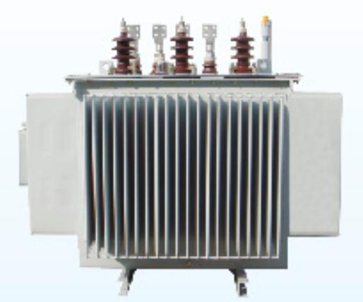
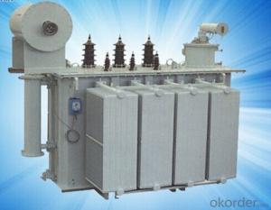
6-10kV Oil-immersed DistributionTransformers

1. Introduction
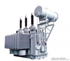
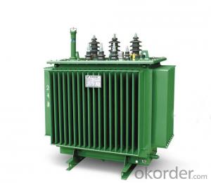
6-10kV oil-immersed distributiontransformers with capacity 30-3150kVA are suitable for 6-10kV distributionnetwork system. Product complies with GB/T6451-2008 standards.
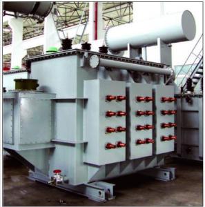
Type 9, 11 and 13 are classified byloss standard. Two types of oil tank are provided, they are sealed corrugatedradiating and sheet radiator. Voltage can be adjusted with load through switchinstalled.
2. Characteristics
Fully sealed corrugated tank has corrugatedsheet for transformer oil natural cooling. There is no oil storage cabinetneeded, so the oil is completely isolated from air. This design slows down theaging of oil, eliminates maintenance and extends the transformer life.
3. Technical parameters
Technical parameters of S9-Mcorrugated tank transformers
Code | Rated capacity (kVA) | rated voltage(kV) | Loss (xW) | Short Circuit impedance (%) | No Load Current (%) | Connection Symbol | Weight (kg) |
Dimension L*W*H (mm) | mm | |||||
HV | LV | No Load | Load | |||||||||||
Body | Oil | Total | ||||||||||||
S9-M-100 | 100 |
10 6.3 6 | 6.3 6 | 290 | 1500/1580 |
4.0 | 1.8 |
Yyn0 Dyn11 | 285 | 105 | 515 | 800x680x1030 | 550/550 | |
S9-M-125 | 125 | 340 | 1800/1890 | 1.7 | 355 | 110 | 625 | 920x700x1060 | 550/550 | |||||
S9-M-160 | 160 | 400 | 2200/2310 | 1.6 | 420 | 130 | 740 | 970x730x1070 | 550/550 | |||||
S9-M-200 | 200 | 480 | 2600/2730 | 1.5 | 475 | 160 | 825 | 1020x740x1085 | 550/550 | |||||
S9-M-315 | 315 | 670 | 3650/3830 | 1.4 | 710 | 205 | 1200 | 1350x740x1115 | 550/550 | |||||
S9-M-500 | 500 | 960 | 5150/5410 | 1.2 | 925 | 285 | 1575 | 1470x795x1310 | 660/660 | |||||
S9-M-630 | 630 | 1200 | 6200 |
4.5 | 1.1 | 1085 | 320 | 1835 | 1540x830x1360 | 660/660 | ||||
S9-M-800 | 800 | 1400 | 7500 | 1.0 | 1375 | 435 | 2340 | 1630x920x1430 | 820/820 | |||||
S9-M-1000 | 1000 | 1700 | 10300 | 1.0 | 1480 | 485 | 2600 | 1755x1035x1450 | 820/820 | |||||
S9-M-1250 | 1250 | 1950 | 12000 | 0.9 | 1760 | 575 | 3135 | 1870x1120x1540 | 820/820 | |||||
S9-M-1600 | 1600 | 2400 | 14500 | 0.8 | 2125 | 700 | 3795 | 1970x1170x1645 | 820/820 | |||||
Technicalparameters for S11-M corrugated tank transformers
Code | Rated capacity (kVA) | rated voltage(kV) | Loss (xW) | Short Circuit impedance (%) | No Load Current (%) | Connection Symbol | Weight (kg) | Dimension L*W*H (mm) | mm | ||||
HV | LV | No Load | Load |
|
|
| Body | Oil | Total |
|
| ||
S11-M-160/10 | 160 |
10 6.3 6 |
0.4 6.3 6 | 280 | 2200/2310 |
4.0 | 1.6 |
Yyn0 Dyn11 | 490 | 100 | 795 | 1135x713x180 | 550/550 |
S11-M-200/10 | 200 | 340 | 2600/2730 | 1.5 | 540 | 175 | 880 | 1168x738x1200 | 550/550 | ||||
S11-M-250/10 | 250 | 400 | 3050/3200 | 1.4 | 665 | 200 | 1025 | 1240x780x1240 | 550/550 | ||||
S11-M-315/10 | 315 | 480 | 3650/3830 | 1.3 | 730 | 220 | 1155 | 1300x835x1265 | 550/550 | ||||
S11-M-400/10 | 400 | 570 | 4300/4520 | 1.2 | 895 | 300 | 1390 | 1390x905x1310 | 550/550 | ||||
S11-M-500/10 | 500 | 680 | 5150/5410 | 1.1 | 1025 | 360 | 1650 | 1470x965x1365 | 550/550 | ||||
S11-M-630/10 | 630 |
0.4 | 810 | 6200 |
4.5
5.5 | 1.0 | 1650 | 415 | 2260 | 1575x1010x1430 | 660/660 | ||
S11-M-800/10 | 800 | 980 | 7500 | 1.0 | 1510 | 470 | 2550 | 1685x940x1545 | 820/820 | ||||
S11-M-1000/10 | 1000 | 1150 | 10300 | 0.9 |
Dyn11 | 1640 | 650 | 3070 | 2180x1075x1655 | 820/820 | |||
S11-M-1250/10 | 1250 | 1360 | 12800 | 0.8 | 2010 | 820 | 3700 | 2310x1310x1715 | 820/820 | ||||
S11-M-1600/10 | 1600 | 1640 | 14500 | 0.8 | 2420 | 990 | 4470 | 2460x1514x1920 | 820/820 | ||||
S11-M-2000/10 | 2000 | 2240 | 16830 | 0.8 | 2860 | 1120 | 5050 | 2782x1600x2040 | 820/820 | ||||
S11-M-2500/10 | 2500 | 2640 | 19550 | 0.8 | 3195 | 1155 | 5912 | 2500x2060x2010 | 820/820 | ||||
Parameters for 6-10kV SZ11 OLTC Transformers
Code | Rated capacity (kVA) | Rated voltage (kV) |
| Loss(xW) | Short Circuit impedance (%) | No Load Current (%) | Connection Type Symbol | Weight (kg) | Dimension L*W*H(mm) | mm) | ||||
HV | LV | No Load | Load | Body | Oil | Total | ||||||||
S11-M-200/10 | 200 |
10 6.3 6 |
0.4 |
±4x2.5%
| 0.48 | 3.06 |
4.0 | 1.5 |
Yyn0 Dyn11 | 531 | 241 | 1058 | 1510x820x1460 | 550/550 |
S11-M-250/10 | 250 | 0.56 | 3.60 | 1.4 | 630 | 350 | 1400 | 1740x1020x1440 | 550/550 | |||||
S11-M-315/10 | 315 | 0.67 | 4.32 | 1.4 | 860 | 280 | 1630 | 1790x1050x1570 | 550/550 | |||||
S11-M-400/10 | 400 | 0.80 | 5.22 | 1.3 | 910 | 400 | 1740 | 1830x1120x1630 | 660/660 | |||||
S11-M-500/10 | 500 | 0.96 | 5.21 | 1.2 | 1080 | 460 | 2068 | 1900x1230x1780 | 660/660 | |||||
S11-M-630/10 | 630 | 1.20 | 7.65 | 1.1 | 1396 | 611 | 2661 | 2010x1320x1930 | 660/660 | |||||
S11-M-800/10 | 800 | 1.40 | 9.36 | 1.0 | 1650 | 780 | 3220 | 2280x1370x2220 | 820/820 | |||||
S11-M-1000/10 | 1000 | 1.70 | 10.98 | 1.0 | 2083 | 843 | 4240 | 2170x1160x2320 | 820/820 | |||||
S11-M-1250/10 | 1250 | 1.95 | 13.05 | 0.9 | 2390 | 1100 | 4950 | 2510x1310x2630 | 820/820 | |||||
S11-M-1600/10 | 1600 | 2.40 | 15.00 | 0.8 | 2900 | 1065 | 5235 | 2570x1382x2650 | 820/820 | |||||
Note: The above parameter before slash is forYyn0 connection type and after slash is for Dyn11 connection type.
- Q: does anybody know what Transformers 2: Revenge of the Fallen is going to be about? Like what is the whole plot, or storyline?
- The battle for Earth has ended but the battle for the universe has just begun. After returning to Cybertron, Starscream assumes command of the Decepticons, and has decided to return to Earth with force. The Autobots believing that peace was possible finds out that Megatron's dead body has been stolen from the US Military by Skorpinox and revives him using his own spark. Now Megatron is back seeking revenge and with Starscream and more Decepticon reinforcements on the way, the Autobots with reinforcements of their own, may have more to deal with then meets the eye. I'd take that with a pinch of salt though as it's probably fan invented.
- Q: I have a US Navy Plate and Filament Transformer Manufactured by Hudson American Corporation.This monster weighs 14.5lbs, and is in a sealed steel casing.There are 16 unlabeled terminals, and I'm working to identify those.It does however have the current and voltage labelings for the primary and secondaryPrimary : 110/115/120v AC (Since there are 16 taps, I'm guessing that these are separate primaries)Secondary 1:360-0-360 200MA DCSecondary 2: 6.6v 10A CTSecondary 3: 12.6V 3ASecondary 4: 5.25V 3AI'm set on using a solid state rectifier circuit so i don't need the 5.25V Line, or the 12.6V line.Could I somehow do something to get extra current on the B+ line (S1 windings) with these unused secondaries?I want 4x 6550/kt88, so the extra plate current would be great to have around.
- Get get right of entry to to an impedence meter and degree what the transformer relatively is (impedience clever). you will discover small transformers with an identical turns ratio and not additionally be near to what you like. If there's a marking on the transformer , you're waiting to seem it up. the different element is that utilising tubes at very low voltages would positioned you into very non linear tiers of operation. the entire thought of utilising a triode or a tetrode amp is for a tube sound and to get low distortion or controled distortion. beginning at 5 to ten% distortion isn't great. i assume you're speaking approximately utilising something like a 3V4 or in all possibility between the tubes designed for listening to aids. Neither replace into designed for finished constancy. Microphonics are a controversy. there are a number of integrated amplifiers that are very low distortion and could no longer require an output transformer.
- Q: I have a transformer with serial number T.K.K EHT 66001 S-2. I confused with input (primary) wires. it has 5 wires (white red brown yellow and blue). which wires is used for 220 vac?? please help.
- It looks like you MAY have an auto-transformer, ie only one winding. Off hand, I would say the white is supply live and blue the common return. If you measure the DC resistance of White to all the others and record reading. Then red to all others as above and same with brown, yellow and blue. The pair with highest reading Should be the primary, it doesn't really matter which is live or neutral, as long as you take the return of the secondary to the neutral. The other 3 wires will give you 3 different voltages with respect to neutral, however the EHT in the serial No. May indicate Extra High Voltage, which is not 220v. by any stretch of the imagination. Is there no information whatsoever on the transformer itself? Clear as MUD I know, but I'm not good at explaining things. Your meter should be at the lowest range, as this is DC resistance you are measuring, not AC.
- Q: I have 14 gauge wire and some 28 gauge wire. Do both lengths of wire have to be insulated? Is it as easy as winding the 14gauge wire top to bottom and then do the 28 gauge wire top to bottom also? I'm guessing this is a step up transformer because the battery is going through the 14 gauge wire and then the lightbulb is hooked to the 28 gauge wire?Does the direction on winding matter at all? Say, CW for the 14g and then CW with the 28 gauge?
- ferrite rods are not customarily used for transformers. at RF they are sometimes used as a core for a loop antenna. your application sounds like an ignition coil as you need an interrupter on the DC input (like points on a car ignition). the primary wire (14 gauge) would just be a few turns and not likely to run the full length top to bottom, the secondary (28 gauge) would be a lot of turns like 10 or 20 times as many. direction of winding would not matter in this application as capacitive coupling between the windings should be insignificant. all wire has to be insulated as a shorted turn spoils the transformer effect. wire used for transformers is customarily insulated with lacquer as plastic adds too much bulk to make tight windings. if you already have bare wire, then you made have some success by dipping the wire in lacquer paint first. it sounds like you are duplicating a project you have seen elsewhere. without knowing the source, it is hard for us to guess what the circuit parameters need to be for the transformer. but as i pointed out initially, i am skeptical that you will get this to function in the manner you are expecting. AC power transformers of the kind that use these wire gauges always use a torroidal core ferrite, never a rod. static DC cannot be transformed at all.
- Q: Hi, I'm trying to build a Jacob's ladder or maybe a Tesla coil. What should I use to get enough voltage? A lot of resistors or a transformer? (Are they also safe for humans?)
- No, you could die. Resistors do not increase voltage. Transformers do. However, you can also get high voltages via a Van de Graff generator, although a big one can still be dangerous.
- Q: Do you think transformers is a good movie?Whos your favourite team autobots or decepticons?Whos your favourite transformer?And whats the best scene in the film?
- Transformers was a AWESOME MOVIE!, but it really annoys me when people tell me that the only thing good was the special affects. It takes really talented actors to play only on green screen, and the acting was very funny AND dramatic. My favorite are the Deceptions, just cause they have those really small things that can turn into stuff. I can't remember what they were though. My favorite transformer is Bubblebee, because it can talk through the radio which when I was kid was what I wished I could do. I my favorite scene probably is when the Autobots are causing mayhem while Sam is trying to find the glasses. I love it that Mojo peed on that one.
- Q: I am going to see Transformers 3 today with some friends. Can someone give a detailed summary of what happens in Transformers 1 and 2 because i haven't seen them. Thanks to whoever helps.
- Transformers: Plot - Autobots and Decepticons travel to Earth to find the AllSpark, launched into space by Optimus Prime from Cybertron millions of years ago, and found by a team of scientists who kept it, and a frozen Megatron hidden underneath Hoover Dam for seventy years. The key to finding it rests with a teenage boy, Sam Witwicky. Character list (major players, for time's sake) Humans: Sam Witwicky, Mikaela Banes, Capt. William Lennox, TSgt. Robert Epps, Rachel, Special Agent Simmons, Secretary of Defense Keller * (deceased) Autobots: Optimus Prime, Jazz*, Bumblebee, Ironhide, Ratchet Decepticons: Megatron* (will return), Starscream, Barricade, Bonecrusher*, Blackout*, Scorponok, Frenzy* Transformers: Revenge of the Fallen Plot - The Fallen, a rogue Transformer and also a Prime, sets out with a revived Megatron to find the Matrix of Leadership in order to power the Sun Harvester, built thousands of years ago by the Dynasty of Primes in order to siphon a massive supply of energon from the sun. By turning this machine on, the sun will be totally drained of energy and turn Earth into a frozen wasteland. To succeed, the Decepticons must first kill the only one who can defeat the Fallen, Optimus Prime, and capture Sam, who unconsciously knows the way to the Matrix. Humans; Sam, Mikaela, Lennox, Epps, Graham (the British NEST soldier), General Morshower, Simmons, Leo, Director Galloway Autobots: Optimus Prime* (does return), Bumblebee, Ironhide, Jetfire*, Wheelie, Ratchet, Jolt, Elita-1, Arcee, Chromia, Mudflap, Skids, Sideswipe. Decepticons: The Fallen*, Megatron, Starscream, Grindor*, Sideways*, Ravage*, Devastator*, Rampage*, Pretender Alice*, Demolisher*, Soundwave, The Doctor, Scorponok*, numerous Decepticon soldiers.*
- Q: i study transformer and found calculation for pf for open/short circuit test. but the value is bit confusing.pf at open test: 0.182pf at short tets: 0.135what the value means??why we need that??
- Power Factor is very important , u know (apparent power)^2(active power)^2+(reactive power)^2 and also Iactive powerIIapparent powerI*cos(phi) phi is the angle between the voltage and current in transformer , and power factor is cos(phi) active power can transfer through the transformer(and also can transfer to mechanical power and torque in motors) but the transformer get the reactive power and send it back to the input power line,reactive power get back to heat of wires and voltage drop in power lines. so we like that reactive power be minimum (reactive powerapparent power*sin(phi)) or pho----0 then the cos(phi)----1 most of motors have power factor about 0.8-0.95 that is very good the value pf0.182 means the angle between the voltage and current vector is acos(0.182)79.5 at open test u have a very bad transformer it just transfer %18.2 of the apparent power
- Q: I have a Whirlwind microphone splitter box with a direct out and a transformer isolated output. What's the reason for the transformer isolated output?
- A mic splitter is used when you have to feed two different mixers (for example, a front of house and monitor mixer). The main reason for the transformer isolation is to prevent ground loops. You've heard 'emthat 60Hz hum you get when audio equipment is connected incorrectly. The transformer breaks the direct connection between the mic and the second mixer. The mic will get it's ground through the direct connection to the first console. Another benefit is that loading is reduced on the mic. This preserves the frequency response. Also, the transformer isolation prevents any weirdness if phantom power happens to be turned on at both mixers. Back to ground loops now. If instead of using an iso box, you simply Y'd the connections all together, here's what could happen. With that scenario, you've now tied the grounds of two different mixes together. Now, each mixer had it's own path to ground through the 3rd pin of the AC power cable. Now, they have 2 pathsthrough the AC power cable and through the shield of the mic cable and back through the other console. When you get a loop like that, current flows and causes hum, possible shocks, all kinds of nasty things. That's why in audio the 1st commandment is Thou shall have one and only one path to ground. One final pointalways use the direct output of the iso box first. Otherwise, your mic isn't grounded. Greetings from Austin, TX Ken
- Q: I have two-way transformer (120Vlt;240V) that has a surge capacity of 2000W and a continuous capacity of 1600W. The transformer is plugged into my wall socket and is, on its output side, attached to a power surge protector that leads to six separate sockets. There are periods where not all six sockets are in use - in this specific case, the only appliance is a 50W fan - and my question is, does the transformer still eat 1600W off my meter and waste most of it as heat, or is it nice and intakes maybe only 60W and inefficiently converts it to the required 50W? If the company/model comes into question, I can only say the transformer is of Taiwan origin - the company logo is a 'Z' with small D intersecting the two parallel lines of the former letter, all against a blue background - and has a model number of TC-2000. Many thanks.
- ok so most transformers are able to use almost 100% efficiency because of their advanced technology. Like optimus prime - he's badass
Send your message to us
Oil immersed Distribution Transformers 6-10kV
- Ref Price:
-
- Loading Port:
- China Main Port
- Payment Terms:
- TT OR LC
- Min Order Qty:
- -
- Supply Capability:
- -
OKorder Service Pledge
OKorder Financial Service
Similar products


Hot products


Hot Searches
Related keywords

