
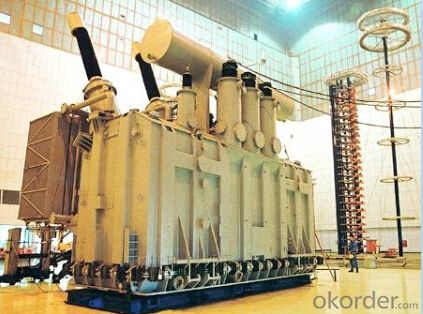
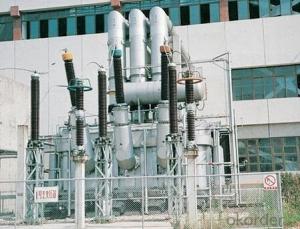
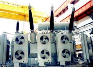
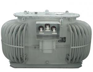
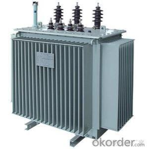
400MVA/230kV power transformer exported to USA
- Ref Price:
-

- Loading Port:
- Tianjin
- Payment Terms:
- TT OR LC
- Min Order Qty:
- 1 pc
- Supply Capability:
- 1 pc/month
OKorder Service Pledge
OKorder Financial Service
You Might Also Like


Quick Details
| Place of Origin: | HeBei | Brand Name: | CNBM | Model Number: |
|
| Usage: | Power | Phase: | Three | Coil Structure: | Toroidal |
| Coil Number: | 3 Winding | Capacity: | 50000 63000 80000 100000 120000 180000 | Rated Voltage: | 400MVA/230kV |
| Connection Symbol: | YNd11 Dyn11 YNyn0d11 | Tank: | Cover type or Bell type | OLTC: | MR or ABB or SMS |
Packaging & Delivery
| Packaging Detail: | Mainbody --naked Disassembled parts -- crate |
| Delivery Detail: | 3 months |
Specifications
1. CESI certificate
2. High short-circuit withstand
3. Low loss, PD and noise
4. CTQC certificate
5. No leakage
Description
The application of the 400MVA/230kV power transformer can significantly improve the economy of the UHV substation, and matches well with the transmission capacity of UHV lines, which has wide prospect of application. Because of its large capacity and large volume, the whole transportation weight with nitrogen is about 470-490 tons, and due to the restricted transport conditions, the transportation becomes the critical issue for application of 400MVA/230kV power transformer. In order to make the products applicable to any UHV substation in our country, the state grid of corporation of China set the "A study of easy-transport large capacity UHV Transformer” as a key scientific research projects, and entrusted BTW to carry out the research.
During the process of research and development, BTW adopted the advanced design technology and modular design, the transformer can be transported disassembly and with advantages of compact core and winding body, less transportation weight and low transportation cost, effectively solves the need of UHV construction in the transportation restricted areas. By using the most advanced 3D magnetic field calculation software, BTW performed detailed analysis and calculation for the magnetic flux leakage and eddy current loss of the transformer coil, iron core and oil tank steel structures. Besides, by using of the advanced electric field calculation software, BTW performed detailed analysis and calculation of main longitudinal insulation, and mastered the arrangement of the main longitudinal insulation of large capacity UHV transformer and the control of distribution of winding magnetic flux leakage. All of which make the products with low loss, low noise, small volume, strong anti short circuit ability, no local overheating and other significant advantages, and guarantee the long-term safe and stable operation.
The world's first on-site assembled large capacity UHV Transformer’s right at the first time once again filled the gap in the field of UHV transformer research after Chinese transformer industry overcame the difficulty of integral transport of the 400MVA/230kV power transformer, which marks BTW has fully occupied the world transformer industry technical peak. The successful development of the product filled the gaps in the domestic technology and met the urgent need of UHV construction application in our country, greatly improved the technical level and manufacturing ability of BTW in terms of UHV Transformer products.
- Q: I have a 120v-36v transformer hooked up to a bridge rectifier composed of 4x IN4004 diodes, 2 filter capacitors and a 100k resistor paralleling them as a bleeder resistor. The rectifier puts out the full 50v DC I expect it to, but at the same time the transformer faintly vibrates (you can only really tell if you touch it), and over time it gets quite hot. Why is this? I have checked over my connections quite a few times and I am 99.9% sure its all connected properly.
- As Bill R says for working it out. As to how to answer in an exam, First write what is known, and what is wanted down. Write the appropriate equation(s) down and substitute values/simplify equation down as far as possible, you haven't been given all the information required to get that answer in the question. If you don't have all the data provided, and aren't expected to make assumptions then I'd argue the correct answer is actually the formulae produced when you've correctly put all that known in. But quite often you ARE expected to make reasonable assumptions. Sometimes an exam might have a cover page with assumptions to be made (if you don't make them you'll not get the answer right) sometimes you've just got to know how to make reasonable assumptions without being told. as it's 60Hz mains you're probably in the US. I'm in the UK so would it be reasonable for me to assume 50Hz mains if I were sitting the exam here? In cases where you have to make assumptions, it's usually a good idea to then state you are making an assumption. I suggest showing the difference which can happen if f is at least two different values eg finish with assuming f50Hz as mains is in the UK, then C needs to be C1followed on the next line by assuming f60Hz as mains is in the US, then C needs to be C2If you were feeling a little annoyed at those who wrote the exam, and wanted to make your point extra clear you might even throw in the case of f 120Hz. I believe many aircraft alternators generate AC at that f. Ask your teacher/lecturer about what kind of assumptions you might be expected to make. If they skirt around the issue maybe quote some Charles Babbage, and hope they laugh at the sarcasm ' On two occasions I have been asked,—Pray, Mr. Babbage, if you put into the machine wrong figures, will the right answers come out? I am not able rightly to apprehend the kind of confusion of ideas that could provoke such a question.' —Charles Babbage, Passages from the Life of a Philosopher
- Q: If load loss of a transformer at full load is 100kW, the load loss at 50% load will be a) 50kW b) 75kW c) 25kW d) 100kW. i think its 25kW because load loss is inversely proportional to the square of loading percent. kindly explain . is it right.
- I'm guessing load loss is the same as copper loss, which is due to the resistance of the wire in the transformer. This loss is (I^2)(R wire) so the answer is c) 25 KW The current is 50% at 50% load, I^2 0.25
- Q: Transformers of the three transformations are the three?
- Do not know you specifically refers to the meaning, in general, the transformer can change the voltage, variable current, variable phase
- Q: Design a control circuit to step-up/step-down the voltage either in primary or secondary side of the transformer. The tapping (step-up/step-down) of the transformer must be auto controlled by VB program.For example, suppose if the desire voltage in the secondary of the transformer is 15V, but because of the loss, the voltage might drop to 12V. So, a sensor is used to detect this drop and send the message to VB. VB will process the message and send the reply signal to control circuit so that the voltage will step up (compensated) to 15 V. If the voltage exceeds 15 V, VB has to rectify it also.Can anyone please show me some guidances or circuit diagram of this project? Thank you!!!!
- Thank okorder
- Q: I have a 240v-5v transformer for recharging, and it makes an annoying very high-pitched squeaking noise. What causes the noise?
- SQUEEK? That sounds like a high (audio) frequency oscillator. So this sounds like a pulsed regulator, not like a transformer-type power supply. I would guess that your unit is measuring the battery voltage, then applying a pulse of power to charge the battery, then checking the voltage again in a continuous sequence. This would be a switching type charger. 5 Volts - sounds like a personal electronics unit, for instance a cell phone or personal entertainment. Right? 240 Volts - Sounds like Europe. Right? (In America it would either be 120 Volts or some switching supplies are designed to operate from 90 to 250 Volts.)
- Q: What is the reason why the dry transformer is loud
- 500kva below the dry-type transformer noise 56 to 58 dB or so, 630kva above 62 to 65 dB or so! This is our factory data. The dry-type transformer sound is great. Big like cattle called the same, because the core is loose!
- Q: I just saw the mythbusters use a neon transformer to spark a methane explosion and the arch looked like a continuous irredecent light. So are neon transformers a part of neon lights? That and if you know, what is the inert gass inside the lights?
- Those are good answers except nothing to do with is incorrect. Neon is a generic term for several gases and vapors used for advertising lighting.The transformers are used for other purposes as they are less costly than transformers optimized for most other purpose. Some of them are designed for as little as 100 volts ac input. Neil
- Q: A topic that: a three-phase transformer wiring is YN, Y, a0, d11, all mean what? Three-phase transformer how four ways to connect it?
- If the three-phase transformer has four windings can not have four kinds of wiring way?
- Q: if the transformer in a wall charger steps down the voltage from my wall to 120V does this mean i could use it in the reverse direction as a step up transformer? I want to combine 4 car batteries making 48V and plenty of amperage, but what can i use to get it up to 120V for my 1/2 hp motor?
- Not you can't really because transformers need AC (alternating current) to work. So your charger has got a rectifier in it and possibly some kind of a regulator circuit. You could use 10 car or motor bike batteries in series to get 120 VDC but PLEASE BE CAREFUL. You could get a nasty shock at 120 volts.
Send your message to us
400MVA/230kV power transformer exported to USA
- Ref Price:
-
- Loading Port:
- Tianjin
- Payment Terms:
- TT OR LC
- Min Order Qty:
- 1 pc
- Supply Capability:
- 1 pc/month
OKorder Service Pledge
OKorder Financial Service
Similar products
Hot products


Hot Searches
Related keywords

