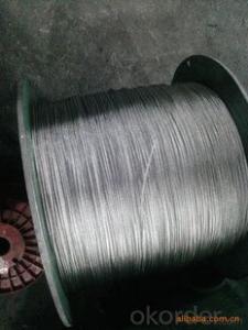
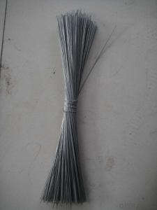
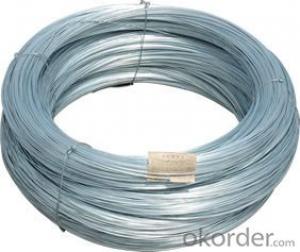
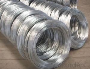
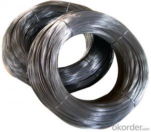
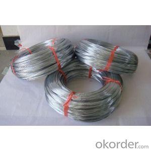
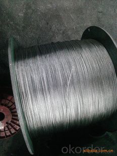
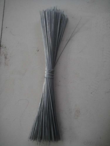
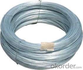
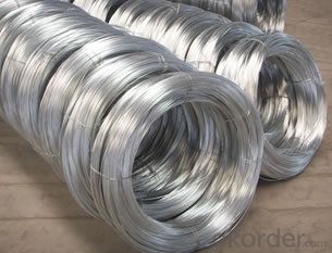
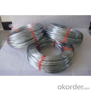
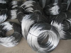
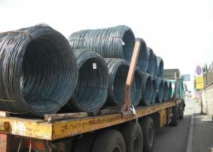
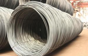
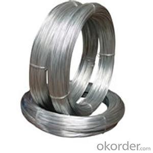
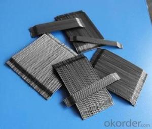
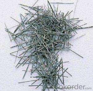
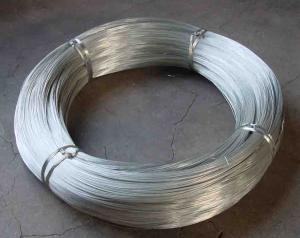
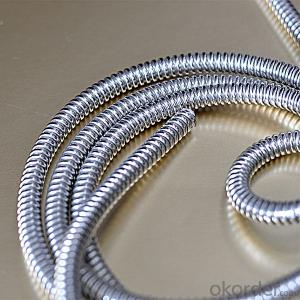
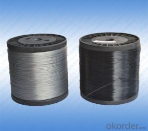
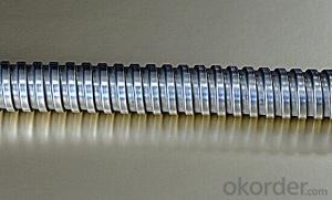
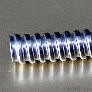
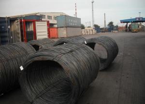
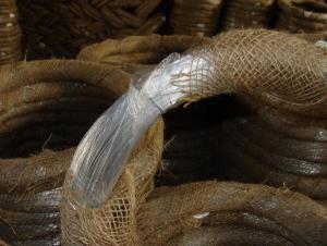
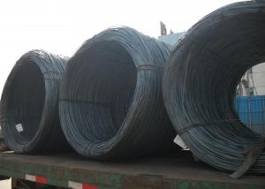
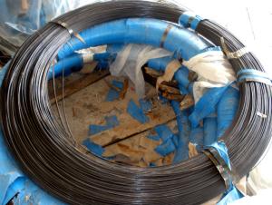
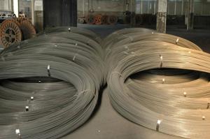
Galvanized Steel Wire for Flexible Duct of cnbm
- Loading Port:
- China main port
- Payment Terms:
- TT OR LC
- Min Order Qty:
- 1 m.t.
- Supply Capability:
- 1 m.t./month
OKorder Service Pledge
OKorder Financial Service
You Might Also Like
Quick Details
| Steel Grade: | Steel | Standard: | ASTM,BS,GB | Wire Gauge: | 0.65mm--2.2mm |
| Place of Origin: | Jiangsu China (Mainland) | Type: | Drawn Wire | Application: | Construction,Automotive System; Wire Rope |
| Alloy Or Not: | Non-alloy | Special Use: | Cold Heading Steel | Model Number: | 0.65mm--2.2mm |
| Brand Name: | Rayee | Packing: | Roll packing, Z2 packing | Surface of Steel Wire: | Bright; Galvanized |
| Manufacturing Capacity: | 600 tons per month |
Packaging & Delivery
| Packaging Detail: | STANDARD EXPORT PACKING OR AS PER CUSTOMER REQUEST |
| Delivery Detail: | WITHIN 7-10DAYS AFTER CONFIRMING YOUR ORDER |
Specifications
Galvanized Steel Wire
wire diameter:0.2-5.6mm
zinc coating:30g-260g/m2
Tensile strength: HIGH
Galvanized Steel Wire for Flexible Duct
1.MATERIAL:10#-80# STEEL
2.DIAMETER: 0.2MM-5.6MM
3.SURFACE TREATMENT:ELECTRO GALVANIZED,HOT DIPPED GALVANIZED
4.ZINC COATING: 40G/M2 - 300G/M2
5.PACKING:ROLL PACKING WITH PLASTIC SPOOL INSIDE, POLYWOVEN BAG OUTSIDE
STANDARD Z2 PACKING
OR PRODUCE AS YOUR REQUESTS
PLS FEEL FREE TO CONTACT US
| Nominal Diameter | Minimum number of reverse bends | Minimum number of Torsions (Bright and Class B) | Minimum mass of coating (g/m2) | ||||
| (Bright and Class B) | |||||||
| 1770 Mpa | 1960 Mpa | 2160Mpa | 1770 Mpa | 1960 Mpa | 2160Mpa | Class B | |
| over 0.6mm ~incl. 0.65mm | 11 | 10 | 9 | 28 | 25 | 23 | 60 |
| over 0.65mm ~incl. 0.70mm | 10 | 9 | 8 | 28 | 25 | 23 | 60 |
| over 0.70mm~incl. 0.75mm | 16 | 15 | 14 | 28 | 25 | 23 | 60 |
| over 0.75mm~incl. 0.80mm | 15 | 14 | 13 | 28 | 25 | 22 | 60 |
| over 0.80mm~incl. 0.85mm | 13 | 12 | 11 | 28 | 25 | 22 | 70 |
| over 0.85mm ~incl. 0.90mm | 12 | 11 | 10 | 28 | 25 | 22 | 70 |
| over 0.90mm~incl. 0.95mm | 11 | 10 | 9 | 28 | 25 | 22 | 70 |
| over 0.95mm ~incl. 1.00mm | 10 | 9 | 8 | 28 | 25 | 22 | 70 |
| over 1.00mm ~incl. 1.10mm | 17 | 16 | 14 | 26 | 23 | 21 | 80 |
| over 1.10mm ~incl. 1.20mm | 16 | 15 | 13 | 26 | 23 | 21 | 80 |
| over 1.20mm ~incl. 1.30mm | 15 | 14 | 13 | 25 | 22 | 20 | 90 |
| over 1.30mm ~ incl.1.40mm | 13 | 12 | 10 | 25 | 22 | 19 | 90 |
| over 1.40mm ~incl.1.50mm | 11 | 10 | 9 | 25 | 22 | 19 | 100 |
| over 1.50mm ~incl. 1.60mm | 14 | 13 | 12 | 25 | 22 | 19 | 100 |
| over 1.60mm ~incl. 1.65mm | 13 | 12 | 11 | 25 | 22 | 19 | 100 |
| over 1.65mm~incl. 1.70mm | 13 | 12 | 11 | 25 | 22 | 19 | 100 |
| over 1.70mm~incl. 1.80mm | 11 | 11 | 10 | 25 | 22 | 19 | 100 |
| over 1.80mm ~incl. 1.85mm | 10 | 10 | 8 | 24 | 21 | 18 | 100 |
| over 1.85mm ~incl. 1.90mm | 10 | 10 | 8 | 24 | 21 | 18 | 115 |
| over 1.90mm~incl. 2.00mm | 9 | 9 | 7 | 24 | 21 | 18 | 115 |
- Q: i have my wires installed by a professional, and i wanted to put an taco switch to run to my amp, if i run a taco switch will it be okay? and with messing up the wires that he already ran would it screw it up?
- I take it you want to put a togo switch to be able to turn your amp on and off? Sure you can . Put it inline with the blue remote turn on wire. Then when you flip the switch the amp will power on . Flip again and it will turn off.
- Q: I have DirectWay and have a wireless router. I recently hardwired my computer in because I kept losing signal. The distance between my computer and the router is about 30 ft. But since I hardwired my computer in, it seems slower than when I ran the wireless adapter, i.e downloading videos and music. I was under the impression that wired was faster. What gives????
- That's odd that you said wired seems slower. Generally the wireless connection is the slower of the two. I've never seen wireless faster than wired if all things are equal. Perhaps something else is causing the slow down. Don;t know what to tell you to check. Is your eathernet cable good quality? the 30 ft distance is pretty short and shouldn't cause a slow down. Hope that helps
- Q: I keep trying to strip this damned wire but the copper wire inside the tubeing constantly ends up getting split apart instead of staying together. Im pretty sure Im doing it right Ive done it before easily. The wire is very old though could that be the problem?
- There is isia tool called wire stripper available in tools store.Buy one and use it.It can be adjusted for different guague of wires,it cuts only insulation not the copper wire inside,
- Q: what gauge wires should i use for my 12'' alpine typr r SWR-1242D?
- 4 guage amp kit This one is the best SoundQuest SQK0 1/0 Gauge Copper-Clad Aluminum Wiring Kit Technical Details * 1/0 Gauge Power and Grounding Wires * Remote Wire, Speaker wire, and RCA Signal Wires * Fuse Block and Fuse * Various crimp style connectors
- Q: I removed a dishwasher and now the wires are exposed. I turned off the circuit to that outlet. I am planning on waiting a while to replace the dishwasher. I want to turn the circuit back on so I can use the other outlets, but don't want to leave the wires exposed. Any ideas?
- wire nuts that can hold 1 .. 14awg wire or a bit smaller... twist one on each individual wire and give it a little tug, it sould not come out, then wrap some electrical tape around each of them
- Q: electrical wire prices
- It follows the copper market. During high economic growth periods, copper (for wiring) oil for fuel are both simultaneously in high demand.
- Q: Ok I've been changing the old outlets in the house and all of them were fine until I got to this 1 outlet. The outlet had 1 ground wire, 2 white and 2 black (if that helps). The wires were a little chewed up looking so when I went to wrap the upper white wire to its screw it broke and now the wire won't reach the screw and certain lights in the house won't turn on because of it. I probably should have left it alone because of the condition of the wires but its too late now so how do I go about getting the wire to reach its screw ? Thanks
- using a wire nut just get the same size wire cut it about 4 inches long and make whats called a pig tail use the wire nut to connect the new wire to the short one its most likley a 14/2 wire if its on a 15 amp breaker if its on a 20/amp you should use a 12/2 wire
- Q: I just bought an aftermarket cd player for my Grand Cherokee and I would rather not have to cut and strip wires so I want to get an wiring harness adapter. My question is, can I just get any wiring harness adapter or do I need the direct connection adapter that is specifically made for Chrysler to Kenwood?
- Doug is spot on, but missing one thing that im going to add in real quick. The wiring harness makes things simper because it is color coordinated with the aftermarket wire radios. Some chrystler/dodge/jeep come with an existing amplifier that must be bypassed in order to have sound come through the speakers. Lucky this bypass is easy as connecting a wire. (quick note, buy only metra install kits- wiring harness and dash kit) On the wiring harness there will be a blue wire (not to get confused with the blue wire from the radio) coming off of it. This needs to be hooked up with the red wires, or the blue wire from the radio's wiring harness which is the amp remote wire. This bypasses the amp.
- Q: I have eight speaker wires, I can figure that out on my own. I also have a red/blue stripe, black/red stripe, black/white stripe, and blue. Which ones are the power wires?
- I found this online. I can't promise it's 100% correct. best of luck! Car Radio Battery Constant 12v+ Wire: Blue/Red Car Radio Accessory Switched 12v+ Wire: Blue/Black Car Radio Ground Wire: Black Car Radio Illumination Wire: Red/Black Car Stereo Dimmer Wire: N/A Car Stereo Antenna Trigger Wire: N/A Car Stereo Amp Trigger Wire: N/A Car Stereo Amplifier Location: N/A Car Audio Front Speakers Size: N/A Car Audio Front Speakers Location: N/A Left Front Speaker Positive Wire (+): Violet Left Front Speaker Negative Wire (-): Blue/Orange Right Front Speaker Positive Wire (+): Blue/White Right Front Speaker Negative Wire (-): White Car Audio Rear Speakers Size: N/A Car Audio Rear Speakers Location: N/A Left Rear Speaker Positive Wire (+): White/Blue Left Rear Speaker Negative Wire (-): Red/Blue Right Rear Speaker Positive Wire (+): White/Green Right Rear Speaker Negative Wire (-): Blue
- Q: I accidently spilled soda all over a bunch of wires and controllers. I cleaned the controllers off and they're not sticky, but what should i do about the wires?
- Specify wires.
Send your message to us
Galvanized Steel Wire for Flexible Duct of cnbm
- Loading Port:
- China main port
- Payment Terms:
- TT OR LC
- Min Order Qty:
- 1 m.t.
- Supply Capability:
- 1 m.t./month
OKorder Service Pledge
OKorder Financial Service
Similar products
Hot products
Hot Searches
