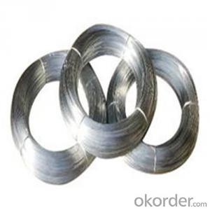
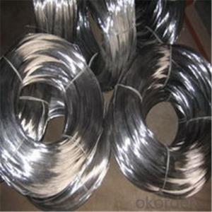
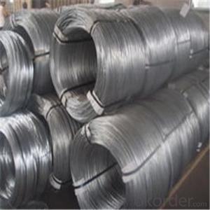
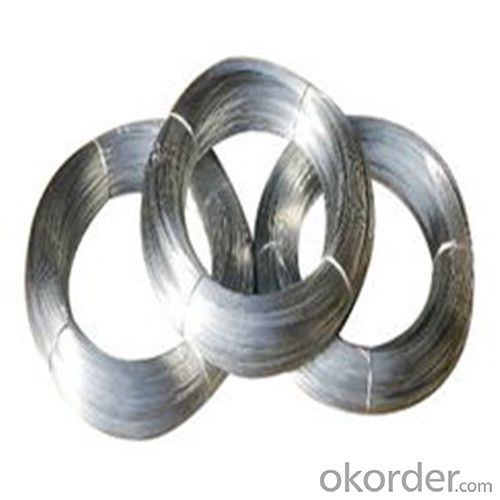
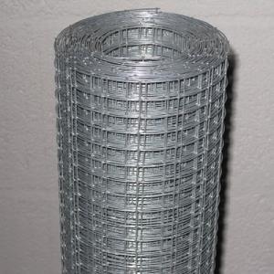
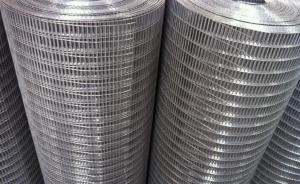
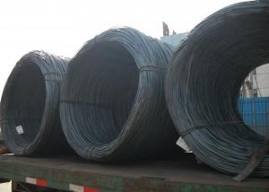
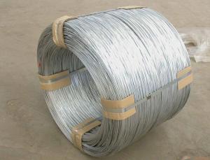
Galvanized Iron Wire /Binding Wire Using in Making Welded Mesh
- Loading Port:
- Tianjin
- Payment Terms:
- TT or LC
- Min Order Qty:
- 10 m.t.
- Supply Capability:
- 5000 m.t./month
OKorder Service Pledge
OKorder Financial Service
You Might Also Like
1.Structure of Galvanized Iron Wire Description:
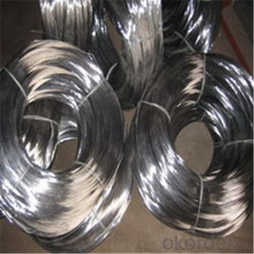
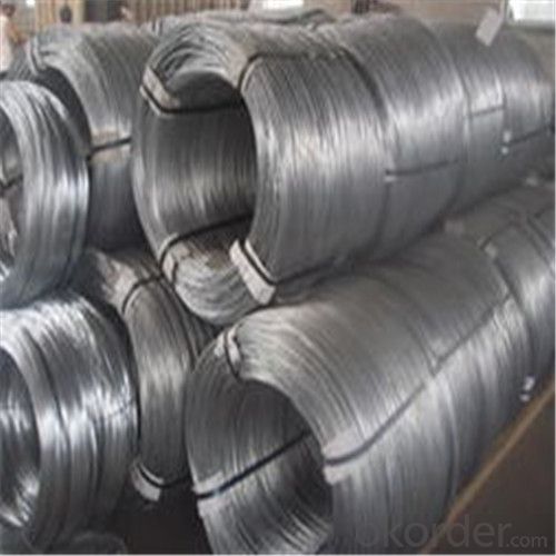
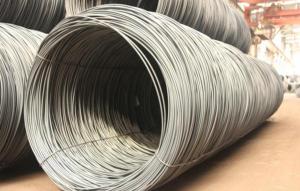
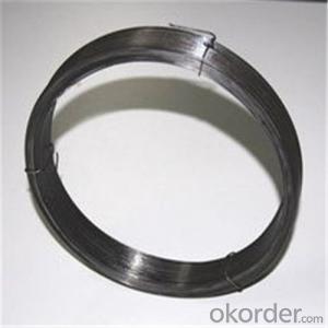
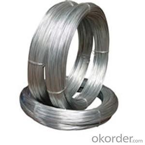
Galvanized Iron Wire is also known as galvanized wire or galvanized steel wire. We produces galvanized wire at diameter ranging from 0.14mm to 5.0mm, which can be supplied in the form of coils, spools, U type wire or straightened and cut into tie wire. Electric Galvanized Iron Wire we produce usually goes through standard processes under careful control from steel rod coil, wire drawing, annealing, rust removing, acid washing, boiling, drying, zinc feeding to wire coiling.
Through wire drawing, wire galvanizing and other processes,Galvanized iron wire has the characteristics of thick zinc coating, good corrosion resistance, firm zinc coating, etc. The process is Steel rod coil -- Wire Drawing -- Wire Annealing--Rust Removing-- Acid Washing-- Boiling-- Drying-- Zinc Feeding-- Wire Coiling.
2.Main Features of Galvanized Iron Wire:
• Durable
• Good Visual
• Convenient
• Use widely
• Antirust
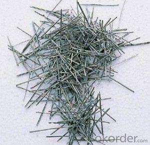
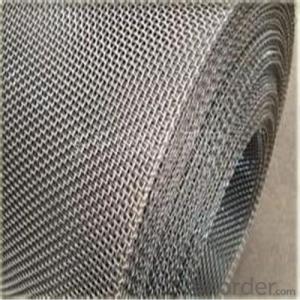
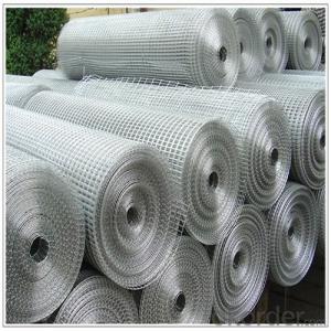
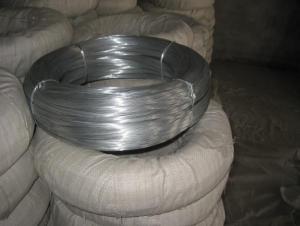
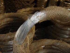
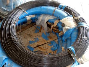
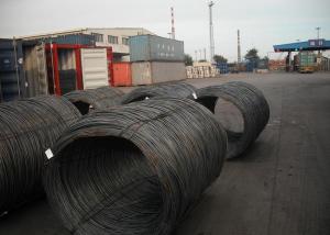
3. Galvanized Iron Wire Images
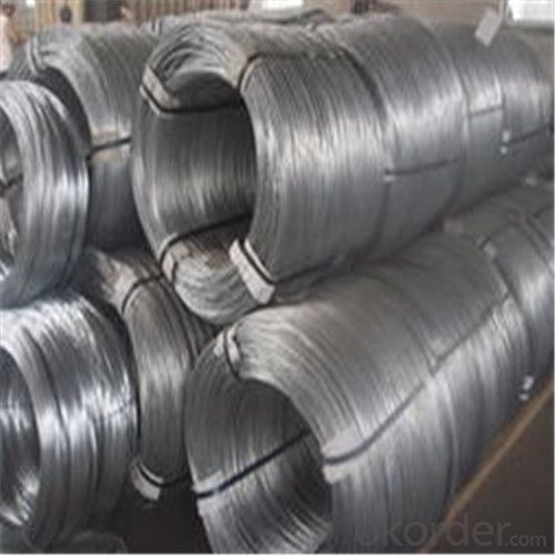
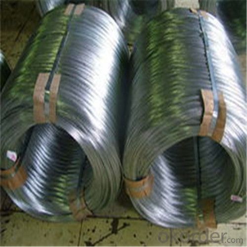
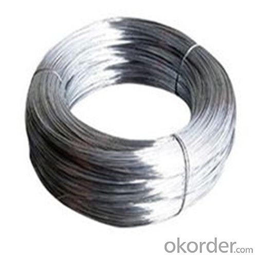
4. Galvanized Iron Wire Specification
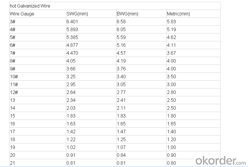
5.FAQ
We have organized several common questions for our clients,may help you sincerely:
①Are you facotry of trading company?
We are a facotry and supplying wire products for over 10 years.
②What is different of the Hot-dipped and Electro galvanized iron wire?
Hot-dipped Iron Wire:
1. This kind of wire is extensively used in construction, handicrafts, woven wire mesh, express way fencing mesh, packaging of products and other daily uses.
2. Hot dipped galvanized iron wire can be supplied in the form of coil wire, spool wire or further processed into straightened cut wire or U type wire. Galvanized iron wire is made of Low carbon steel wire Q195.
Electro Galvanized Iron Wire:
1.Electro galvanized iron wire can be supplied in the form of coil wire, spool wire or further processed into straightened cut wire or U type wire.
2. Electro galvanized iron wire applications:
Electro galvanized iron wire is mainly used in construction, express way fencing, binding of flowers and wire mesh weaving.
Electro galvanized iron wire, electro galvanized steel wire, electro galvanized Wire.
③How much the transportation freight will be for the samples?
The freight depends on the weight and packing size and your area.
- Q: i am putting in a ceiling fan. there is a black wire and a white wire along with a copper looking wire in the wall. on the fan there is a blue,white,and green. where do i connect this to the wires in the wall? running from a wall switch btw
- connect the fan black wire and the fan blue wire to the house black wire. then connect the white fan wire to the white house wire. connect the short green wire from the fan and fan bracket to the copper wire. the blue is the power wire to the light on the fan. Good luck...
- Q: wiring has ceramic poles
- This is one time I'd say life was much more important than the savings of heat and cooling. Your wiring is too old, probably brittle for any kind of activity up there. Just get some new wire and install it before messing with the insulation. Then if you have enough left over install what insulation you can.
- Q: what wires are my speaker wires going to and coming from the factory amp and how do i hook them up please help i drive a 96' ford exploder
- aamp of america has a psa interface part# BHA 5511. It works great The other way is to rewire from the psa to the radio. The psa is over the r rr wheel well (a real pain in the butt to get to)
- Q: What type of wire do i need to install a normal inside wall outlet? Do i have to use solid copper wire?
- Buy AWG # 14X2 cable inside includes one more bare copper wire for grounding. Solid single conductor is the common product.
- Q: A potential difference of 13 V is found to produce a current of 0.37 A in a 3.1 m length of wire with a uniform radius of 0.42 cm.(a) What is the resistance of the wire? (b) What is the resistivity of the wire? Please show work.
- P. D. applied = V = 13 V Current produced = I = 0.37 A (a) Resistance of the wire = R = V / I = 13/0.37 = 35.14 Ohm (b) R = ρL/A = (ρL) / π r?) = ρ = (R A) / L = R (π r?) / L ......... (1) R = Resistance of the wire = 35.14 Ohm , L = length of the wire = 3.1 m A = Area of cross-section of the wire = π r? r = radius of cross-section of the wire = 0.42 cm = 0.0042 m ρ = Resistivity of the wire in Ohm-m Substitute the values in the formula (1) and calculate. Take π = 3.14
- Q: I need to wire a single 120v outlet from the 240v volt wire I use on my compressor. Im installing a 120v electric automatic drain valve on my large shop air compressor. The compressor is wired up with SJ00W 10-AWG, 4-wire power cable (red,green,black white wires). and is rated at 240v @ 15-amp(compressor not wire). The drain valve uses a normal house hold current wiring config. (black,white and open copper)The 240v power supply is the only supply I have near by, (two of them actually) Or I would just wire the automatic valve off an outlet and call it a day. So How do I wire a 120v 3-wire set up from the 240v 4-wire supply? Thanks
- Hud is correct. To accomplish this you would need to install a 30 amp subpanel with a 4 to 6 circuit configuration with a two pole breaker for feeding the compressor with # 10 wire and a one-pole 15 or 20 amp breaker with smaller wire (14 or 12 gauge respectively and the appropriate rated 120 volt outlet on that branch circuit). If you have regular 120 volt outlets somewhere nearby (as I think you are saying in your second to last sentence) I would go that route instead.
- Q: So I know that the neutral wire is the 'return wire'. But why does my textbook say that it has the potential to have the same amount of electricity as the live wire (if the wiring is faulty)? But essentially, if the wiring is not faulty it is technically safe to touch it, it has 0 volts.Could someone explain this to me?
- The electricity supply mains has three wires. They are called Live, Neutral and Earth The Live wire is connected directly to the generators of the electricity supply company. NEVER touch this wire, it carries 230 Volts and can kill you!! The Neutral wire returns the electricity to the generator after it has passed through the appliance, to complete the circuit. The Neutral wire is at approximately zero volts but you must NEVER touch this wire either!! If the wiring is faulty it may be carrying the same electricity as the Live wire. The Earth wire usually carries no electricity, it is there as a safety device. If something in the appliance goes wrong, or it is wired incorrectly, then the Earth wire may be carrying the same electricity as the Live wire. To be completely safe, NEVER touch this wire either!!
- Q: hi to all, pls try to help me,, to get the kawasaki zxr250 cdi color wiring diagram!?i hope that you help me..i really hope that i use my kawasaki big bike,.....thank you !!!!!rose,,
- Wiring diagrams are always black and white. Do you need a wiring diagram for your bike, or do you just want one in color?
- Q: The spark plug wire on my dirt bike needs to be replaced because it was touching the exhaust and it burned through.I was wondering if the ignition coil and spark plug wire are one piece and need to both be replaced or is there someway to disconnect spark plug wire? They spark plug wire doesn't seem to be pluged in, but it seems to be one piece. Does anyone know?
- The coils/wires I have dealt with have been replaceable. The coil has a spike in the hole the wire goes in and a retaining nut. The resistor cover is usually hard plastic[Bakelite?] and has a small screw inside the hole so you can screw the wire onto.
- Q: I removed my old door chime/bell a few years ago and replaced it with a wireless one. That one quit working and now I am attempting to install a new wired one again. The only problem is, when I removed my old one way back, I failed to label the existing wires to where they go. I have two wires coming out of my wall mount, one white, one brown and the both have a white and red wire sticking out of them. I am not sure which one/ones will connect to the FRONT and TRANS posts on my new chime. I don't have a rear door bell button so that is not a problem. Which wire goes to the FRONT and TRANS and do I cap off any of the 4 wires? My installation instructions don't cover the mindless mistake of not having the wires labled.
- Garage door springs are part of the garage door itself, not the garage door opener. That said, it must also be added that the springs make it much easier to raise and lower the door. They generally last a long time, and they have only one function. But over time, all that lifting, through all those weather changes, tend to weaken the metal and lead to a break. In my case, the springs appeared to be original to the house, which means they've been at work since 1956. Once you understand that long record of service, it becomes a little hard to complain when they finally break down. And break down they did. It was a Sunday afternoon, and we were sitting around the quiet house reading. Suddenly, we heard a large noise that sounded like a very heavy object had fallen on the roof, or maybe a car had driven into the side of the house. I quickly started hunting around for the cause, and couldn't find a thing. So much noise, and no noticeable cause? Didn't make sense . . . until I went out later and tried to open the garage door. Even then, it took me some time to figure out that the spring had split. Once I discovered it (see photo), I knew I'd found the source of the noise. With a broken spring and a solid wood door to a two-car garage, you really can forget about opening the door. I couldn't lift it more than an inch.
Send your message to us
Galvanized Iron Wire /Binding Wire Using in Making Welded Mesh
- Loading Port:
- Tianjin
- Payment Terms:
- TT or LC
- Min Order Qty:
- 10 m.t.
- Supply Capability:
- 5000 m.t./month
OKorder Service Pledge
OKorder Financial Service
Similar products
Hot products
Hot Searches
Related keywords
