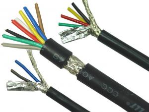
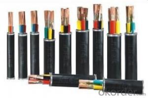
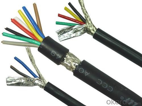
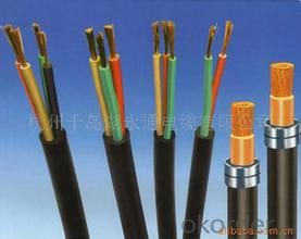
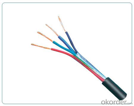
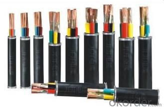
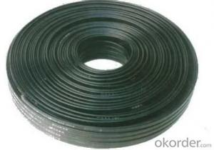
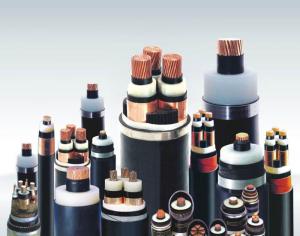
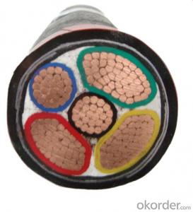
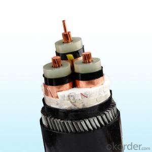
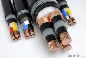
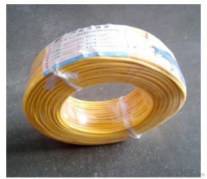
0.6/1kv 2core XLPE Insulated Steel Tape Armoured PVC Sheathed Electrical Power Cable
- Loading Port:
- China main port
- Payment Terms:
- TT or LC
- Min Order Qty:
- 100 m
- Supply Capability:
- 20000 m/month
OKorder Service Pledge
OKorder Financial Service
You Might Also Like
0.6/1kv 2core XLPE Insulated Steel tape Armoured PVC Sheathed Electrical Power Cable
LOW VOLTAGE 0.6/1KV
2C YJV YJLV
This cable is suitable for use in fixed installation with rated voltage 0.6/1 kv Electricity transmission and distribution lines. Can be use in both indoor and outdoor.
For use in laying indoors, in tunnels, in underground ducts, in conduits or buried directly. Can withstand mechanical damage but couldn't withstand pull force.
.
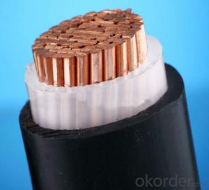
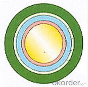
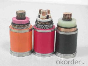
DESIGN
Conductor:plain annealed electrolytic copper(Hard drawn aluminum available)
Insulation: XLPE
Filler: PP rope/tape
Wrap Tape: Non-woven fabrics
Bedding: PVC
Armour: steel tape armoured
Outer sheath: PVC
Color: Black
( Note: XLPE: crosslinked polyethylene, PP: polypropylene, PVC: Polyvinyl chloride )
CHARACTERISTICS
Electrolytic conductor, class 2 (Circular compacted copper/ aluminum)
Max. temperature of conductor for long-term continious woking: <=90ºC
Max. working temperature in case of short-circuit: <=250ºC ( max. time 5s )
Meter by meter marking
Chemical and oil resistance: excellent
Abrasion resistance: excellent
Flame retardant
Installation Underground
Circumstance temperature when installation: >=0 ºC
Minimum bending radius:
Single-core cable: 20(D+d)±5%(mm)
Multi-core cable: 15(D+d)±5%(mm)
( Note: D: Actual external diameter of cable, d: Actual external diameter of conductor )
The cable could be laid without the limit of altitude difference
Installation in the Air
The center distanceof paralledl laying single-core cables:
cross sectional ares<=185mm2: 2*Dmm (D: diameter of cable)
cross sectional ares<=240mm2: 90mm
Circumstance temperature: 40 ºC
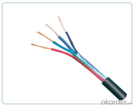
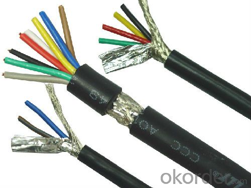
Picture
- Q: Got the door all taken off the hinges. Now I'm stuck on how to get the electric stuff unplugged. I can kind of see how to unplug it, but it's down a hole and I'm afraid I won't be able to reconnect the new wiring on the new door. Help please?
- you can splice the wires and use longer wires to reattach. most the time if you can get a long flat head screw driver down their they are plastic holders that hold them, pry them off and you should get more length.
- Q: Does anyone know what the voltage means on electrical wire sheathing? Some 14AWG wires show 600V and others are 800V.I have a burnt wire that shows 1000V.They are all 14AWG, stranded, copper wire. I just don't know what the voltage rating means. Does the wire support up to that many volts or does the sheath resist heat better the higher the number is?
- Wires have a whole bunch of specifications. The metal, copper or aluminum…what is the current carrying capacity under a given set of circumstances… The insulator, the jacket For example a wire designed for a heating appliance like a range will not necessarily resist UV, oil…exposure The voltage rating is generally a function of insulation thickness The particular material, rubber, plastic, ceramic, glass, is more related to heat endurance Hope this properly answers your question Guru
- Q: Adventure Island game in the Qi Nepal's Lloyd research mission where to play the wire bag where to play?
- Apple's mobile phone software BUG, try this method, so good to go after the sale! 1) to open the device 2) into the system 3) insert the data line 4) see the "This cable or accessories have not yet been certified, it may not work with this iPad reliable" tips, do not point anything including buttons, direct pull Out of data lines. 5) insert the data line, you will see the prompt, then close the warning message.
- Q: What are the test requirements for the power cord?
- 3 generally showing yellow-red,, blue phase line represents zero, represents the yellow-green ground.
- Q: I have an old farm house with 3 out buildings. The main house has electrical service. One out building has a circuit panel that then feeds to an out building and a barn. The out building with a circuit panel used to have separate electrical service but does not any longer. I would like to run a feeder line from the main house to the outbuilding circuit panel which would then provide power to the barn and additional out building. the distance between the two circuit panels is approximately 120'. there is a standard indoor line that runs most of the way. Can these two boxes be tied together at all? With the standard 12/2 line that is in place? What I would be running off this line is basically lights in the barn and 2-3 computers plus a space heater in the outbuilding.Any ideas?
- There are no code limits on general use receptacles on a circuit, however, you want to try to anticipate potential heavy loads that may be on that circuit all at one time. If you're turning them into bedrooms, you can generally put two bedrooms on a 15amp circuit because the biggest load you'll ever plug in is a vacuum cleaner. If you're only doing two rooms, you'll want at least two circuits just for good measure, not necessarily a code requirement. If window AC units are anticipated (unlikely in a basement, I know) then you'll want a 20amp dedicated circuit for each AC unit. Window ACs draw a lot of amps, and if you have a dedicated circuit for each window AC you could turn that run into a 240v circuit should you purchase a 240v AC. If you're just putting in one ceiling fixture in each room, then the lighting can be on the receptacle circuits. However, if you were going to be putting a whole bunch of recessed fixture (I would if it were me) you can only load a circuit up to 80% because lighting fixtures are considered constant use. So if you figure out the amps that your fixture will draw (figure with the largest wattage bulb installed in the fixture, even if you're not going to use the max wattage bulb) you can only put 12 amps on a 15amp breaker and 16 amps on a 20 amp breaker. Also, for general use receptacles and general lighting we normally run 14 gauge wire since it's easier to pull and work with. 12 gauge is generally for where you know you'll have a heavy load. These days with computers, LED tvs, and cfl and led lighting, peoples homes are drawing less and less energy, in general. You definitely should consider a dedicated 20amp circuit for if you're going to be using space heaters, sump pumps, dehumidifiers, etc.
- Q: 3 * 1.0 square wire can carry much power of the electrical (one-way) Jiqiu! The Thank you! The More
- Mouse and keyboard with wireless. The other line with a tie under the order on it. It's that simple.
- Q: Three-phase (refers to the line of fire, zero line and ground it?) 4 square copper wire 380V voltage, has received a 2P cabinet air conditioning, 3 desktop computers, 3 notebooks, 1 rice cooker, 2 fans, Can I install a 1.5P hanging air conditioner? The wires are laid by dark lines. More
- 1. There is a short circuit in the chassis, automatic protection of the power supply. Re-lock the motherboard and plug the cable (preferably with the smallest system to try) 2. Power itself damage (replacement of power, and then test) By the way to teach you a very effective way is to put All the accessories on the motherboard (cpu, memory ...) removed, boot to see such a fan will not turn, if the turn, then add a fitting, and then test to be measured which is not added to which is not bad
- Q: I have two switches (one controls a fan and one controls a light) in a box with only one feed wire. The normal pigtail split is used for the blacks to the switches and the whites to the light and fan, ground to grounds. I have a timer with a black, red, white and ground that I will use to control the fan. Ground goes to ground, red goes to the fan, black gets connected to the existing blacks, for the white I pigtailed two short white wires with the white feed wire and connected one to the light switch white, and the other to the whites for the the fan and timer white (it works). Now the question Could I have connected the timer white with the whites for feed, the light and the fan or would that have caused a problem, (I thought it would so that is why I split the feed white off with the pigtail)
- It's only a question of what fits in the wire nut. When you buy wire nuts they come with a list of all of the different combinations of wires that will fit in them. Your way is fine - a bit of extra work is all.
- Q: I'm 18 now, but when I was 15 (sophomore in HS), I did a lot of electrical wiring upgrades around my house. I changed the fuse box to a circuit breaker panel when I was 16. That same year, I did some wiring at my girlfriend's house (her dad let me). I installed a ceiling fan in her room and one in her parents' room.Do teen boys typically know how to do this? Or am I the exception?
- That's great you know how to do this but you better hope there's never a fire and it's traced back to unlicensed, amateur electrical work, or the insurance company will NOT pay for the fire damage even if the house burns to the ground. You seem to have the knack, so you really should get licensed if you want to make a career out of this. It certainly pays well.
- Q: Hi, I am building a greenhouse in my backyard and had a few questions as to how i should wire it. The appliances I will have in the greenhouse include.A 400 watt light.a 115 volt pump, an oscillating fanand a ventilation fanI can't remember the wattage of the two fans. But my question is will I need to run more than one wire out to my greenhouse? The wire I have says its max voltage is 600. any tips and advice would be nice.
- Lights and fans don't take a lot of juice - just get some 12-2 wire with ground - you can get stuff you can bury in a trench if you want. Wire this into a 20 amp breaker in your house and run it out to your green house. Come up through the ground in a piece of conduit - and hook this to a big double box - something you can screw securely inside your green house. Make sure you get all your grounds connected nice. And put in two plugins. You can also put in a GFI plugin - and wire the other plugin to it - so that if the circuit blows, it kills the other plugin. That should do it and protect you pretty well.
Send your message to us
0.6/1kv 2core XLPE Insulated Steel Tape Armoured PVC Sheathed Electrical Power Cable
- Loading Port:
- China main port
- Payment Terms:
- TT or LC
- Min Order Qty:
- 100 m
- Supply Capability:
- 20000 m/month
OKorder Service Pledge
OKorder Financial Service
Similar products
Hot products
Hot Searches
Related keywords
