


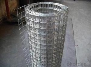
Welded Wire Mesh Electro
- Ref Price:
-

- Loading Port:
- Tianjin
- Payment Terms:
- TT OR LC
- Min Order Qty:
- -
- Supply Capability:
- -
OKorder Service Pledge
OKorder Financial Service
You Might Also Like


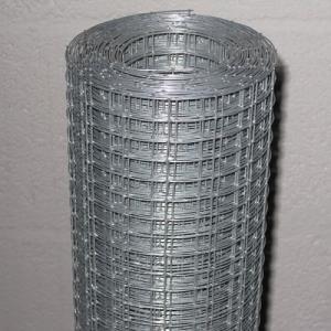
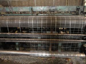
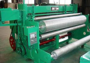
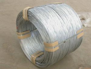
1. Welding style:
Hot dipped galvanized after or before welding
Electro galvanized after or before welding
2. Use:
Welded wire mesh is used in industry and agriculture building, transportation and mining for all such purposes as poultry houses, egg baskets, runway enclosures, draining rack, fruit drying screen, fence.
3.Features of welded wire mesh:
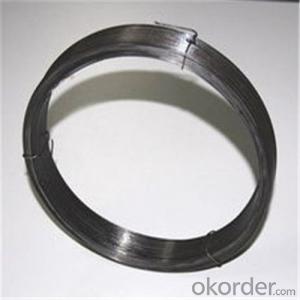
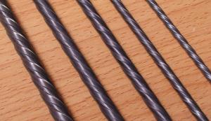
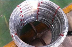
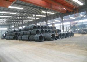
Made of high quality steel wire.
Various configurations and sizes.
Used for the loose strata to avoid falling rocks.
Suitable for shotcrete applications.
Range of sizes to suit roadway width and bolting patterns.
Easy installation
Available in black or hot dip galvanized
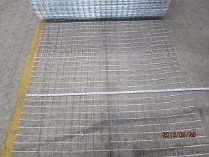
Size of wire aperture: 50x50mm,100x100mm,150x150mm,200x200mm, or according to customer request.
Max length:6mm
Width:1200mm,1700mm,2400mm, or according to customer request.
Diameter of steel wire:3.15mm,4mm,5mm,6mm. or according to customer request
- Q: Or can stranded wire of the same gauge be subsitituted for solid wire without any consequences? The reason I ask is because its for a massive 4kJ capacitor discharge circuit, and I need all the energy delivered to the power coils im using, cant afford to have much leakage inductance.
- Stranded wires have slightly higher inductance than solid wires, but this is noticable only on transmission lines and larger conductors. if you are only using a short conductor, i don't think the inductance of the wire will affect the system, unless the wire is coiled.
- Q: I bought a wiring harness for my 2001 Ford Focus with a non-blaupunkt factory cassette player. The wiring harness doesn't match up exactly. A reviewer online said his didn't match up either, but still worked. The factory wiring has 7 slots and the one I received has 8. What do you think?Factory wiring on the left, the harness I received on the right:Constant Voltage - Constant VoltageGround - NothingIgnition Voltage - Ignition VoltageConstant Voltage - Illumination/DimmerGround, switched - NothingGround - GroundNot Used - Power AntennaNo Slot Here - Remote Turn onIt's mainly the Constant Voltage - Dimmer connection that worries me.And I know I can just hack up the wiring and skip the harness all together, but I'm trying to keep it simple and neat for the next guy/gal (which may be me for all I know).What do you think?Thanks in advance.
- 2001 Ford Focus Car Stereo Wiring Diagram Car Radio Battery Constant 12v+ Wire: Green/Black Car Radio Accessory Switched 12v+ Wire: Black/Pink Car Radio Ground Wire: Black/Green Car Radio Illumination Wire: Orange/Black Car Stereo Dimmer Wire: N/A Car Stereo Antenna Trigger Wire: N/A Car Stereo Amp Trigger Wire: N/A Car Stereo Amplifier Location: N/A Car Audio Front Speakers Size: N/A Car Audio Front Speakers Location: N/A Left Front Speaker Positive Wire (+): Orange/Green Left Front Speaker Negative Wire (-): Blue/White Right Front Speaker Positive Wire (+): Tan/Green Right Front Speaker Negative Wire (-): Green/Orange Car Audio Rear Speakers Size: N/A Car Audio Rear Speakers Location: N/A Left Rear Speaker Positive Wire (+): Gray/Blue Left Rear Speaker Negative Wire (-): Brown/Yellow Right Rear Speaker Positive Wire (+): Black/Violet Right Rear Speaker Negative Wire (-): Orange/Violet
- Q: where does the expression 'down to the wire', come from?
- I found this online: The wire is used in a four-legged footrace-- at least I've only ever heard the word tape used for races involving bipeds. That and ribbon. The wire in question is an actual wire, and it's used in the Sport of Kings, horseracing. A tape or ribbon would be too stretchy to instantaneously trip the shutter on the finishing-line camera when it was crossed. A horse has no problem busting through a single strand of wire.
- Q: Do wired controls work better than wireless? My hubby uses wireless and I wonder if wired would transmit quicker?
- Wired is better. While there is no lag, the battery wearing out in the middle of a game is kind of annoying. If you move too far away from the console, the wireless will not perform.
- Q: the plug only has room for black,red,ground wire.. what do i do with the white wire
- If you have a dryer with a 3 prong cord you can combine the ground and white. Has been done for many decades if you use an older dryer.
- Q: When I cross the black wire and ground I get a spark. Isnthis normal?
- For the best answers, search on this site https://shorturl.im/YcrqW Get one of those screwdrivers that light up when it touches the hot lead. Mark it with black tape, then mark the other with white tape. You can get another tester with 2 wires. Touch one side to the box (metal) and you touch the other to one of the wires. If it lights, that's the hot one. Then touch the other one and you should not see it light. 1- Tape the hot wire with black tape and the common on with white. 2- In the fuse box, the wire that comes off the fuse is the hot one. 3- In a breaker box, the hot wire comes off the breaker screw. Have a real electrician do the wiring and make sure he has a license. If you own your own house, you still need a permit and have the finished work inspected. Good luck !
- Q: can anyone please tell me what does hook-up wire mean and how does it differ from other kinds of wires such as light duty and heavy duty?Also,which one should I use for breadboards?
- Hookup wire is a term usually reserved for wire sizes smaller than 16 AWG, usually single strand conductor. It is generally used in applications where current-carrying capacity is not of prime importance. Breadboarding is one of these applications, but usually uses 22AWG or smaller wire.
- Q: pendant wiring hookup. issue: light is always on house wires: red, white, black, ground pendant wires: green, white, black (and a ground wire to the frame) I did connect red to green, white to white, black to black, ground to ground is connecting the red to green the problem causing the light to be always on? do I just disconnect the red to green to fix?
- No the problem is the black is a constant hot intended for a ceiling fan motor connection. #1) Bare and green are grounds only and no other wire should be attached to them. #2) The red should have been from the switch intended for a light fixture or kit. But it must not be attached to the wall switch or you would have tripped the breaker. I take it there wasn't a light there to start with? Are there any other wires in the ceiling box you didn't mention? If so please edit your question with more detail.
- Q: don't say red because there is no red wire in the 3 wire radio assembly that came stock. there is a yellow wire, black with stripe, and gray with stripe
- 1979 Chevrolet Camaro Car Radio Wire Diagram Car Radio Battery Constant 12v+ Wire: Orange Car Radio Accessory Switched 12v+ Wire: Yellow Car Radio Ground Wire: Black Car Radio Illumination Wire: Gray Car Stereo Dimmer Wire: Light Brown Car Stereo Antenna Trigger Wire: Pink Car Stereo Amp Trigger Wire: N/A Car Stereo Amplifier Location: N/A Car Audio Front Speakers Size: 3 1/2″ Car Audio Front Speakers Location: Dash Left Front Speaker Positive Wire (+): Tan Left Front Speaker Negative Wire (-): Gray Right Front Speaker Positive Wire (+): Light Green Right Front Speaker Negative Wire (-): Dark Green Car Audio Rear Speakers Size: 6″ x 9″ Speakers Car Audio Rear Speakers Location: Rear Deck Left Rear Speaker Positive Wire (+): Brown Left Rear Speaker Negative Wire (-): Yellow Right Rear Speaker Positive Wire (+): Dark Blue Right Rear Speaker Negative Wire (-): Light Blue
- Q: wic iring codes for turner plus three wired to uniden washington cb radio
- Typically there are 3 wires. The shild is ground. Of the remaining two wires, one is push-to-talk and the other is the audio lead. Find the push-to-talk (switch) lead by checking continuity from the shield to each of the other two wires. On one of the remaining two, there will be continuity when the mic is keyed. That is the switch lead, and the other one is audio.
Send your message to us
Welded Wire Mesh Electro
- Ref Price:
-
- Loading Port:
- Tianjin
- Payment Terms:
- TT OR LC
- Min Order Qty:
- -
- Supply Capability:
- -
OKorder Service Pledge
OKorder Financial Service
Similar products

Hot products

Hot Searches
Related keywords

