


Stored Program Repeat Operation Controller Q03UDVCPU CPU Module
- Ref Price:
-

- Loading Port:
- Shanghai
- Payment Terms:
- TT OR LC
- Min Order Qty:
- 1 kg
- Supply Capability:
- 1000 kg/month
OKorder Service Pledge
OKorder Financial Service
You Might Also Like


Specification
Mitsubishi q series universal high speed CPU module q03udvcpu product
specification
[control mode] stored program repeat operation
[input / output control mode] refresh mode (input / output of direct access
mode can be carried out by specifying direct access mode input / output (DX □,
Dy □))
[program language (sequence control program control language)] relay symbol
language, logic symbol language, melsap3 (SFC), melsap-l, function block,
structured text (st)
[processing speed (sequence control program instruction)] LD x0 1.9ns; MOV D0
D1 3.9ns
[constant scanning (function for keeping scanning time constant)] 0.5 ~ 2000ms
(can be set in 0.1ms) (according to parameter setting)
[program capacity] 30K steps (120K bytes)
[memory capacity]
. program memory (drive 0): 120K bytes
. memory card (SD) (drive 2): the capacity of SD memory card (SD / SDHC) that
can be installed (up to 32g bytes)
. standard RAM (drive 3)
When the extended SRAM cartridge is not used: 192K bytes
When using extended SRAM cartridge: capacity when not using extended SRAM
cartridge + capacity of extended SRAM cartridge (maximum 8m bytes of extended
SRAM cartridge)
. standard ROM (drive 4): 1025.5k bytes
. CPU shared memory: 8K bytes
High speed communication area between multiple CPUs: 32K bytes
[maximum number of stored files]
. program memory: 124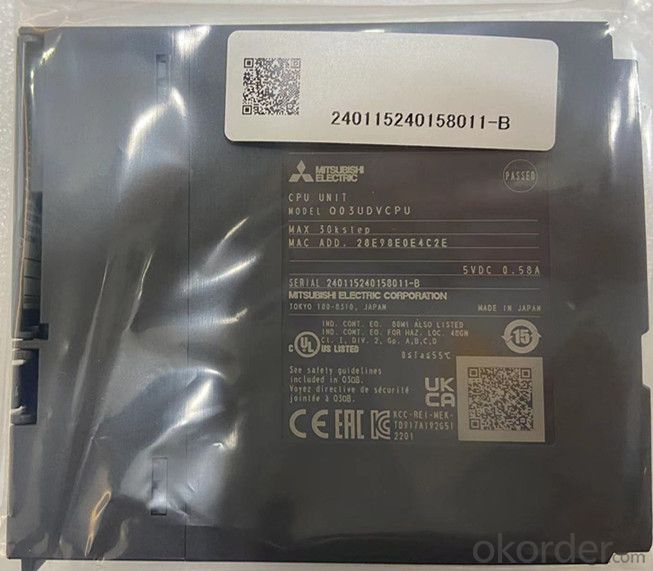
. memory card (SD)
SD: 512 root folders and 65534 subdirectories at most
SDHC: 65535 root folders and 65534 subdirectories at most
. standard ram: 323 when using / not using the extended SRAM card box
. standard ROM: 256
[maximum number of intelligent function module parameters] initial setting
4096, 2048 when refreshing
[write times of program memory] 100000 times at most
[number of writes to standard ROM] up to 100000 times
[number of input and output software components (number of points can be used
in the program)] 8192 points (x / Y0 ~ 1fff)
[I / O points (accessible points of actual I / O module)] 4096 points (x / Y0 ~
FFF)
[specification of built-in Ethernet port of CPU]
. data transmission speed: 100 / 10Mbps
. communication mode: full duplex / half duplex
. transmission method: baseband
. maximum distance between hub and node: 100M
. maximum number of nodes / connections: up to 4 levels for 10Base-T series
connection and up to 2 levels for 100base-tx series connection
. number of connections: 16 socket communication, melsoft connection and MC
protocol in total, 1 for FTP
[latch (hold point) range] l0 ~ 8191 (default value: 8192 points) (the latch
range can be set for B, F, V, t, St, C, D and W) (set through parameters)
[run / pause contact] one point of run / pause contact can be set in x0 ~ 1fff
(through parameter setting)
[allowable instantaneous stop time] 0.58a (CPU module body) / 0.6A (when
installing extended SRAM card box)
[overall dimension h * w * D] 98 * 27.4 * 115mm
[weight] 0.2kg
- Q: Transformers, broken, how to repair
- Some of the transformer buried inside an insurance, first look at the said
- Q: Transformer total circuit breaker rated current 380v, rated current 1000a, the rated capacity and output power how to calculate, I did not learn more points
- Kva is the unit of apparent power, KW is the unit of active power. Apparent power equal to the root number (active square square + reactive power square)
- Q: hi guys can any of you give me advice on wot i need 2do on removing and replacing a faulty line output transformer on a rear veiw projection tv as i have the part and the local tv shop wont fix it 4 me.wot would be the best way to discharge the power from it first and could i jus cut the 2 wires on the old 1 and use connector blocks to connect the new 1 in would this be ok to do or do it need to soilder connected on?. and is there any adjustments that would need to be done to the set when i have it installed be4 i turn it on any help much appreicated
- If you have an identical replacement transformer there shouldn't be a need to adjust anything to start. As to cutting wires to remove the old transformer to replace the new one, I suggest you make yourself a chart of any color coding of the wires or tagging them so there is no error as to what to connect to what on the new transformer. I personally would replace the transformer as the manufacturer installed the original one. As for discharging, use a 10K ohm resistor with one side to ground and the other side of the resistor to the components you want to discharge. I don't advise just grounding direct. Good luck and be careful.
- Q: 1.) What is the function of a transformer?a.) It is a device that can change the voltage of an AC supply.b.) It can change a low voltage supply into a high voltage supply or vice versa.c.) It is a device used mainly to change AC into DC.d.) A and B are correct.2.) What is the function of a transformer at a power station?a.) To convert DC into ACb.) To produce very high voltagesc.) To produce the currents in the power linesd.) None of the above.
- Sorry but I don't know about this
- Q: I have 2 flyback transformers one is from an old TV and the other one is from an monitor (new).I need to know the negative pin for the HV (high voltage)and the pins from the primary coil (input) and primary coil polarity. Can you tell me a method to find out these things? Thank you
- reference 1: The flyback circuit diagram calls for two sets of coils: a primary coil and a feedback coil. The turn ratio is really not that critical so usually ANY two coils in the flyback primary will work. Locate two sets of coils on the horse-shoe-like configured pins by testing the flyback pins for continuity. Often times there are more than two pins connected to a single coil in the transformer. You will need to try the different positions to see which configuration works better for your application. After you have located two independent sets of coils on your flyback, hook them up to the circuit with any polarity. If you turn on the power any you don't hear a whine or hum, try reversing the polarity (switch the leads) of ONE of the coils. If nothing now, reverse the polarity of the other coil. If nothing now, reverse the polarity on the first one you switched again. So the take home message is trial and error. Flybacks can be very picky as to coil polarity because some of them have a rectifier built in them. So try each configuration (8 of them with two sets of coils) until it whines (Occasionally I'll find one that doesn't wine but VERY rarely). Any two sets of coils in a potted flyback should work, so don't try new coils until you're sure you've exhausted all possible combinations. The high voltage will come out of the fat wire from the top of the flyback-usually connected to the CRT with a suction cup. You will not be able to locate the high voltage return pin with a multimeter. The only way to do it is to bring the high voltage line down to the pins and whichever one it arcs like mad to is the one yer looking for. Try to stay away from arcing to any of the pins used for coils. High voltage is not so good for your transistor or power supply. second reference has a lot of useful info plus photos. . .
- Q: I need to find out.I am a huge Transformers fan.
- You can't be a real fan if you haven't watched the original animated series. The movies are crap, they just have nice special effects.
- Q: how to calculate the secondary current of the transformer for example 1200 amps in primary ,primary voltage is 220kv and the secondary voltage is 34.5 kv of the transformer .
- That is a good answer 7652 amps. 7300 amps is more realistic, considering transformer losses, but I don't think any one has built that large a transformer, so surprises are likely. Even at 1% that many amps, 3 phase is likely. Neil
- Q: I am a young electrical engineer and need to review the basics of transformer saturation: conceptually as well as the mathematics and theory behind it.
- Every magnetisable substance behaves like a collection of tiny compass needles, each of which can align itself with an externally-applied magnetic field. P.E. is stored in these compass needles and is released when the field collapses (and the compass needles spring back to their original positions). Since there are only so many of these tiny compass needles in a sample of magnetisable material, there is a limit to how much energy can be stored. Magnetic saturation occurs once all the compass needles are aligned with the external field. An inductor which has become saturated behaves as a simple resistor: it doesn't store energy, just convert it to heat. When a transformer core becomes saturated, the output waveform becomes distorted and the windings get very hot. Steel is generally good for a flux density of 1 - 1.6 Teslas (1 Tesla 1Weber per m?), the better grades being preferred for high-quality mains transformers as they allow cores to be made smaller. (Using a larger core would require more copper wire in the windings; there is a trade-off here.) Ferrites typically saturate at 0.2 - 0.5T, but are much preferred for high-frequency applications since the higher the frequency, the thinner each individual lamination would have to be to avoid eddy current losses.
- Q: I want to multiply current 10times for a second or two. So, is there any easy way to do that without using a high power transformer?Thanx.!
- Current can be multiplied 10 times when using a current transformer with a ratio of 10, such 50/5 amperes. Donut type CTwith a burden of 15 VA.
- Q: how could I describe the physics of transformer?
- A Step up transformer is outdoors a skill station and will enhance the voltage for the skill lines so it may bypass swifter and better parts. A step down transformer is after the skill lines to shrink the voltage and making it secure for domicile use.
Send your message to us
Stored Program Repeat Operation Controller Q03UDVCPU CPU Module
- Ref Price:
-
- Loading Port:
- Shanghai
- Payment Terms:
- TT OR LC
- Min Order Qty:
- 1 kg
- Supply Capability:
- 1000 kg/month
OKorder Service Pledge
OKorder Financial Service
Similar products
Hot products


Hot Searches

