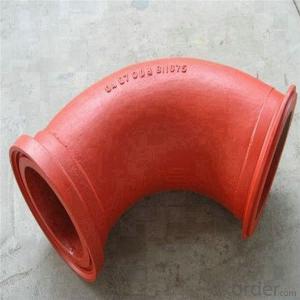
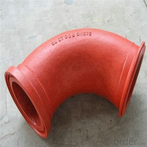
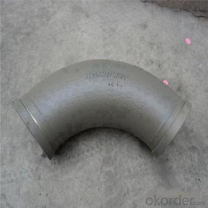
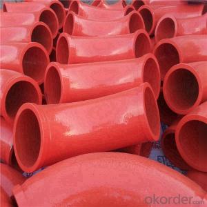
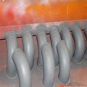
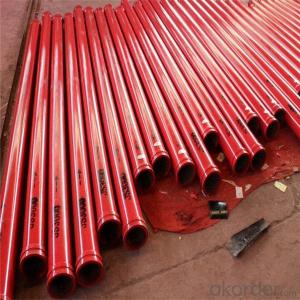
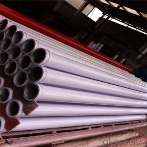
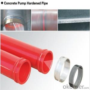
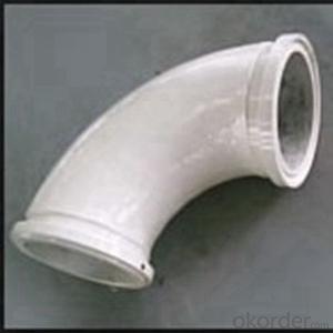
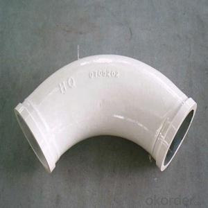
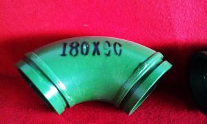
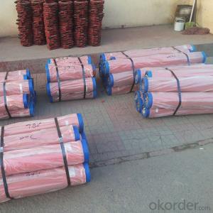
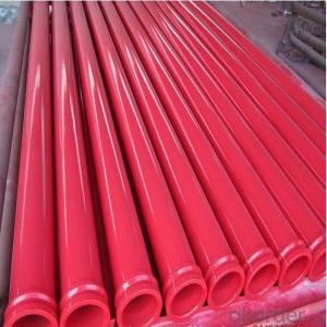
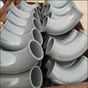
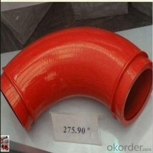
Putzmeister Cast Iron Concrete Pump Pipe Elbow
- Loading Port:
- China Main Port
- Payment Terms:
- TT OR LC
- Min Order Qty:
- -
- Supply Capability:
- -
OKorder Service Pledge
OKorder Financial Service
You Might Also Like
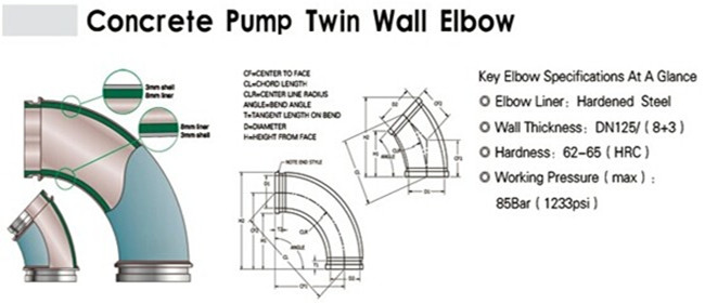
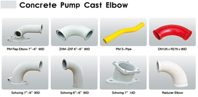
Product parameters:
Name | Material | Specification | Weight | Common life time | Life tine for two end parts | Max work pressure |
Normal bend | ZG40Mn2 | DN125R27590° | 16kgs | 6000-8000m³ | 1000-3000m³ | 126 bar |
Wear-resistant bend | Mn13-4 | DN125R27590° | 16.5kgs | 20000-25000m³ | 2000-7000m³ | 132 bar |
Twin wall bend | Cr20NiCu1Mo+G20 | DN125R27590° | 15kgs | 60000-80000m³ | 20000-30000m³ | 91 bar |
Twin wall bend | GX350+G20 | DN125R27590° | 15kgs | 80000-150000m³ | 40000-50000m³ | 98 bar |
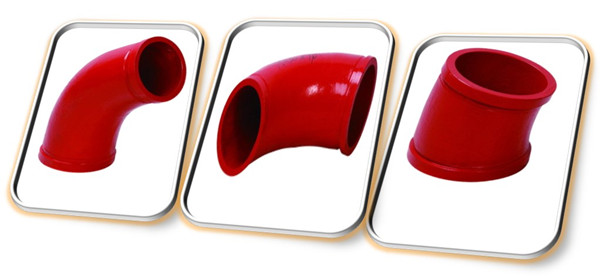
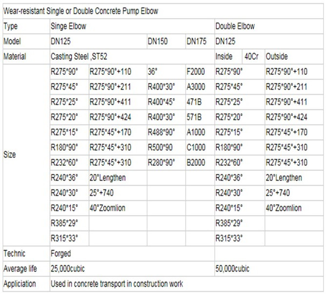
Product Specifications Model:
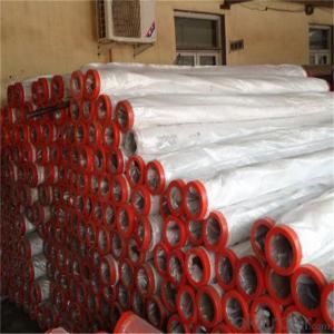
Packaging and transport:
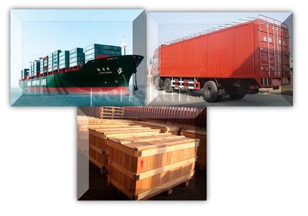
No.1 Export standard packing
No.2 Seaworthy packing
No.3 other ways or according to the customer demand
Why choose us:
1. We are a comprehensive manufacturing and trading company.
2. Our company is one of the biggest manufacturing and trading companies in China.
3. We have been specialized in producing concrete pump spare parts for 10 years and specialized in producing all kinds of concrete pump parts. As Concrete Pump Pipe, Concrete Pump Elbow, Concrete Pump Rubber Hose, Concrete Pump Wear Plate, Concrete Pump S Valve, Concrete Pump Piston and so on.
4. We are famous for our superior quality, competitive prices, first-class craftworks, safe package and prompt delivery.
5. We have been supplying concrete pump parts for SCHWING, PUTZMEISTER, SANY, CIFA, KYOKUTO, ZOOMLION for 10 years, so we can promise you the quality and best price.
- Q: 3D MAX must set motion for each object. Is there a 3D mechanical design software that can simulate the mechanical movement of the parts?As long as the specified object is motor, coupling, chain, gear, into the simulation, the three-dimensional map of the motor shaft will rotate, and drives the coupling, keys, gear for the corresponding movement, rather like 3D Max that is the true state of motion to each object design movement performance of this machine combination?
- SOLIDWORKSBut it is also necessary to develop the law of motion relative to 3DMAX, but your modeling is a problem,Can you NURBS? SOLIDWORKS does not support polygon modelingIf I import the file, there's only line segments. I haven't found a better wayIt's better to continue using 3DMAX
- Q: What are the basic requirements for the design of mechanical parts?
- 2. stiffnessThe elastic deformation of a component at work does not exceed the allowable limit. This is called the stiffness requirement. Obviously, only when the elastic deformation is too large to affect the working performance of the machine, it is necessary to meet this requirement. For this kind of parts, besides the strength calculation, the stiffness calculation must be done.
- Q: The strength criterion of mechanical parts design is briefly introduced
- 1, the strength criterion requires that the working stress of the mechanical parts should not exceed allowable stress [Sigma]. The formula is typical: (3-16) lim - ultimate stress of brittle materials by static stress on the ultimate strength, the static stress of plastic materials, the yield limit of zero stress the fatigue limit. S - Safety factor. 2. stiffness criteria mechanical components are subject to elastic deformation when subjected to load. Stiffness is the ability to resist deformation of materials, mechanical parts, or structures subjected to external forces. The stiffness of the material is measured by the external force required to produce the unit deformation. The stiffness of a mechanical part depends on its modulus of elasticity, E or shear modulus, G, geometry and size, and the form of external forces. It is an important work in mechanical design to analyze the rigidity of mechanical parts. For some parts that need to be strictly deformed (such as wings, machine tools, spindles, etc.), stiffness analysis is necessary to control the deformation. We also need to control the stiffness of the parts to prevent vibration or instability. In addition, a spring, such as a spring, must be used to control its stiffness to a reasonable value to ensure its specific function. The stiffness criterion is that the elastic deformation of a component subjected to load is not greater than the allowable elastic deformation. The expression of the stiffness criterion is (3 - 17) y is an elastic deformation quantity, such as deflection, longitudinal elongation (shortening): [y] is the corresponding allowable elastic deformation. The elastic deformation of a part can be obtained by theoretical calculation or by experiment. The allowable deformation depends on the use of the part, and is determined by theoretical analysis or experience.
- Q: Are they usually steel 45? Under what circumstances do you need special treatment? Such as conditioning? Seek great God pointing! Be deeply grateful!
- Material selection principle is to meet the strength requirements of the premise, the use of the lowest price material.
- Q: Who knows what the design criteria for machine parts are, and how they are designed?
- 5. life standards, in order to ensure that the machine in a certain life span of normal work, in the design of mechanical parts, it is necessary to request the life of mechanical parts. It should be explained that parts can be replaced during the life of the machine, that is, the life of some mechanical parts is shorter than the life of the machine. The life of mechanical parts is mainly affected by fatigue, wear and corrosion of materials. In order to avoid failure caused by parts fatigue, such as fatigue fracture, fatigue strength should be calculated according to the fatigue limit corresponding to the life of mechanical parts. That is to say, according to the requirements of life and the specific speed of parts, according to formula (3-6), the fatigue limit is calculated when the stress cycle number is N. Then the strength condition is calculated and the fatigue strength is calculated. When the fatigue strength is satisfied, the stress cycle times of the mechanical parts can be guaranteed before the damage. Wear is usually unavoidable. Under certain conditions, corrosion is inevitable, such as structural members of bridges, corrosion of buried steel pipelines, etc.. In the design, mainly to ensure the mechanical parts in life, not excessive wear and corrosion. The mechanism of wear is still fully mastered, and there are many factors affecting wear. Generally, the wear resistance of friction pairs is improved according to the tribological design principle. The main measures are as follows: reasonable selection of friction pairs, reasonable choice of lubricant and additives, and control of the working conditions of friction pairs, such as pressure, sliding speed and temperature rise. So far, there is no practical and effective method for calculating corrosion life
- Q: What are the basic criteria for the design of mechanical parts?
- 2. reliable and effective safety protectionAny job of dismantling an old machine is in such a danger that the risk of environmental conditions and the performance of the operator in a dynamic combination is greater when it comes to dismantling the parts of an old machine. As long as there is danger, even if the operator has good technical training and safety education, there are perfect procedures, but also can not completely avoid the risk of mechanical injury accidents. Therefore, a reliable material barrier must be established, that is, to install one or more protective devices, safety devices or other safety measures that are specifically designed to protect the safety of persons. When the equipment or operation of some aspects of the problem, relying on the mechanical safety of their own technical measures to avoid accidents, and ensure the safety of personnel and equipment. Equipment with high risk or high accident rate must be equipped with safety protection device.
- Q: Why do the design of mechanical parts (flanges and elbows) be based on the yield limit?
- In order to reach the yield limit, it is the failure of the material to begin the elasticity, and the elastic-plastic stage has been started. This is designed according to GB150-1998. You can look at the analysis data of the blasting process of the steel
- Q: including design originality, manufacturing process, drawing, processing technology, cost calculation, and function
- That thing has to be paid for, no white lunch. Besides, you say that is a set of design scheme, sometimes involving intellectual property rights of enterprises / if you are the designer, the graduation design, I can tell you sorry, nobody will give you, at least I don't, those things are all mechanical design personnel spent a long time with a lot of effort to get out of the way they want to.
- Q: Are there any standards or specifications for the design of parts list in mechanical design?
- Each company's specifications are not the same, but the general processing parts must have part name, parts drawing number, quantity, material / heat treatment methods (surface treatment methods), remarks, etc.. If purchased, it includes name, model, brand, requirement, remark and so on
- Q: University contact with some simple PLC, ladder diagram, but also to understand.I University of mechanical manufacturing, graduate students made a machine tool parts, mechanical design, University contact with some simple PLC, ladder diagram, but also to understand. Now work in contact with CNC machine tools, want to learn some numerical control system, electrical knowledge, to the job after adding some capital. Online to find some 840D information, that means too hard to see, what NCU, PCU, wiring, address completely do not understand. How do I study?
- NC, with FANUC, specific also don't understand. PLC, there are many brands, there are Ashkenazi SIEMENS, legal genealogy, Schneider, Japanese MITSUBISHI, OMRON, etc., Taiwan Delta, Yong Hong and so on other brands.
Send your message to us
Putzmeister Cast Iron Concrete Pump Pipe Elbow
- Loading Port:
- China Main Port
- Payment Terms:
- TT OR LC
- Min Order Qty:
- -
- Supply Capability:
- -
OKorder Service Pledge
OKorder Financial Service
Similar products
Hot products
Hot Searches
Related keywords
