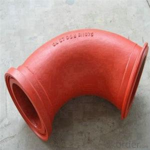

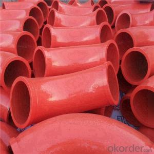
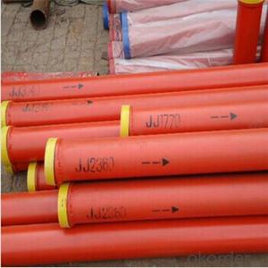
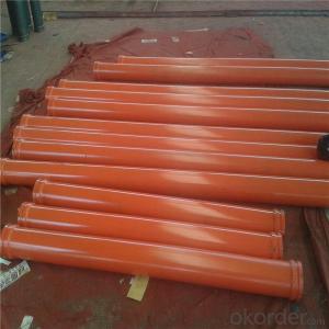
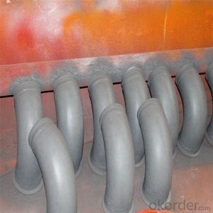
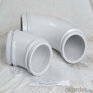
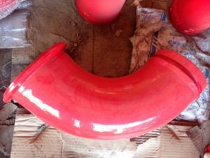
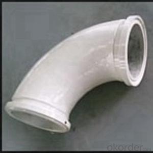
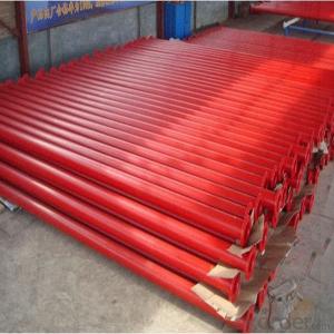
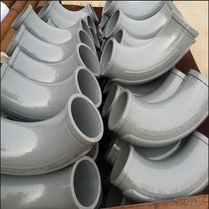
Putzmeister 90D 45D DN125 Concrete Pump Pipe Elbow
- Ref Price:
-

- Loading Port:
- China Main Port
- Payment Terms:
- TT OR LC
- Min Order Qty:
- -
- Supply Capability:
- -
OKorder Service Pledge
OKorder Financial Service
You Might Also Like
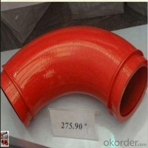
Product parameters:
Name | Material | Specification | Weight | Common life time | Life tine for two end parts | Max work pressure |
Normal bend | ZG40Mn2 | DN125R27590° | 16kgs | 6000-8000m³ | 1000-3000m³ | 126 bar |
Wear-resistant bend | Mn13-4 | DN125R27590° | 16.5kgs | 20000-25000m³ | 2000-7000m³ | 132 bar |
Twin wall bend | Cr20NiCu1Mo+G20 | DN125R27590° | 15kgs | 60000-80000m³ | 20000-30000m³ | 91 bar |
Twin wall bend | GX350+G20 | DN125R27590° | 15kgs | 80000-150000m³ | 40000-50000m³ | 98 bar |


Product Specifications Model:


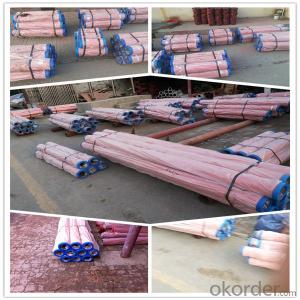
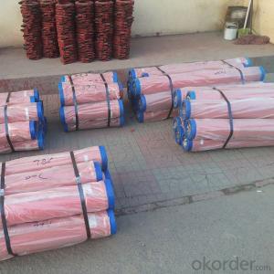
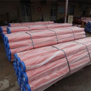
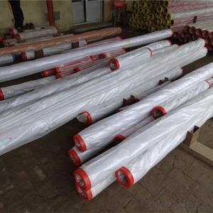
Packaging and transport:
No.1 Export standard packing
No.2 Seaworthy packing
No.3 other ways or according to the customer demand

Why choose us:
1. We are a comprehensive manufacturing and trading company.
2. Our company is one of the biggest manufacturing and trading companies in China.
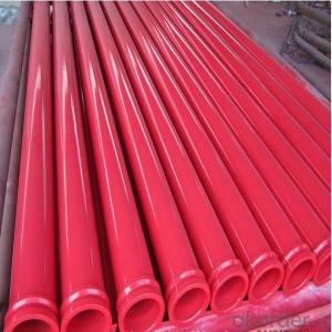
3. We have been specialized in producing concrete pump spare parts for 10 years and specialized in producing all kinds of concrete pump parts. As Concrete Pump Pipe, Concrete Pump Elbow, Concrete Pump Rubber Hose, Concrete Pump Wear Plate, Concrete Pump S Valve, Concrete Pump Piston and so on.
4. We are famous for our superior quality, competitive prices, first-class craftworks, safe package and prompt delivery.
5. We have been supplying concrete pump parts for SCHWING, PUTZMEISTER, SANY, CIFA, KYOKUTO, ZOOMLION for 10 years, so we can promise you the quality and best price.
- Q: In the design of large machinery, it is to design the parts first, the assembly drawings as well
- This is the principle of the overall design process must go through to all aspects of the details, then how do you draw can use computer aided design. Now more flexible. If according to the traditional design from the general to the sub structure, clear whatever you draw.
- Q: Are they usually steel 45? Under what circumstances do you need special treatment? Such as conditioning? Seek great God pointing! Be deeply grateful!
- Material selection principle is to meet the strength requirements of the premise, the use of the lowest price material.
- Q: Does the SolidWorks mechanical design engineer paint parts individually or draw parts in an assembly?
- There are two ways, corresponding to "bottom up" and "top down" two design methods.
- Q: What are the key factors in designing mechanical parts?
- 1- reliability. For example, the design of a transmission shaft, to consider whether the uniform load or impact load, axial load or radial load or both, or combined force. In general, even small loads can be fitted with clearance or transition fit, and tolerances can be enlarged so that processing costs are low. For high speed or large load or impact loads, interference fit should be used, such as flywheel shaft of diesel engine.
- Q: How to design the power assisted robot, mechanical structure and pneumatic part, please point out, thank you!
- 1. pneumatic manipulator mechanical structure can complete the upper, lower, left, right two directions of movement and clamping, pass, to the sub bar, FA pass, looking for Witkey is too simple
- Q: Where are the machine parts designed to be finished?
- To the mechanical processing plant ah, there are many machinery processing plants are based on the processing of parts to others to survive, and our products are parts of those machinery factory processing
- Q: What are the main functions of CAE software commonly used in the design of mechanical products or parts?
- Strength, stiffness, modal analysis, structural optimization, and so on
- Q: What is the significance of using this "three changes" in mechanical design?
- Serialization refers to the same product, under the same basic structure or basic conditions, set out a number of different size seriesGeneralization refers to the parts and components of the same structure and size, which are used in different kinds of products or different specifications of similar products"Article three" the main benefits are: to reduce the design workload, improve design quality and shorten the production cycle; reducing tool and gauge specifications, easy to design and manufacture, thereby reducing the cost; for the organization of standard parts of the scale, specialization, to ensure product quality, material saving, cost reduction; improve interchangeability, easy maintenance; macro management and regulation for the country and in foreign trade; to facilitate evaluation of the quality of products, to solve the economic disputes.
- Q: Can the bearings used in the design of mechanical equipment be used as part drawings?
- Roller bearings do not have to draw part drawings. In assembly drawings, rolling bearings can be drawn in three different ways. These three methods are universal, descriptive and descriptive. The first two kinds are simplified drawing methods. In the same drawing, only one of these two simplified drawing methods is adopted. For the three kinds of law, the national standard "mechanical drawing representation of rolling bearings."
- Q: their own materials, hope that the older generation can be under the guidance of the younger brother, brother, thank you very much
- 1. design is a process of planning, planning, and imagining communicating through visual form.2., human beings transform the world through labor, create civilization, create material wealth and spiritual wealth, and the most basic and important creative activity is creation. Design is the creation of activities that are planned in advance and can be understood as the design, technology, and planning process of any creation.3., first of all, understand the user's expectations, needs, motivations, and understand the needs and limitations of the business, technology, and industry.
Send your message to us
Putzmeister 90D 45D DN125 Concrete Pump Pipe Elbow
- Ref Price:
-
- Loading Port:
- China Main Port
- Payment Terms:
- TT OR LC
- Min Order Qty:
- -
- Supply Capability:
- -
OKorder Service Pledge
OKorder Financial Service
Similar products
Hot products
Hot Searches

