
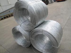

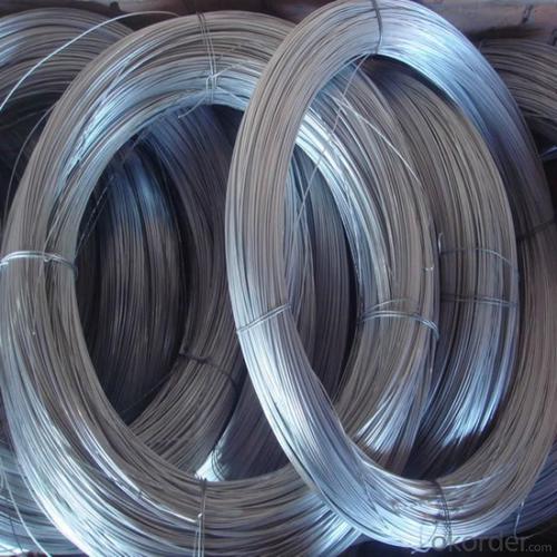


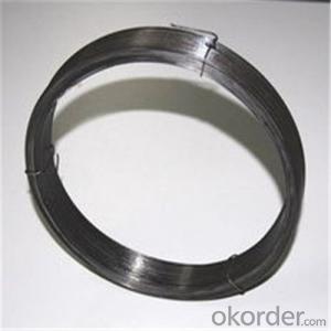
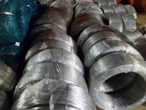
Electro Galvanized Iron Wire For Hexagonal Wire Mesh
- Ref Price:
-

- Loading Port:
- China Main Port
- Payment Terms:
- TT OR LC
- Min Order Qty:
- -
- Supply Capability:
- -
OKorder Service Pledge
Quality Product, Order Online Tracking, Timely Delivery
OKorder Financial Service
Credit Rating, Credit Services, Credit Purchasing
You Might Also Like


 Quick Details
| Place of Origin: | Color: | Model Number: | |||
| Surface Treatment: | Galvanized Technique: | Type: | |||
| Function: | Wire Gauge: | Use: | |||
| Packing: | Finishing: | ||||
Packaging & Delivery
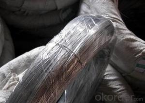
| Packaging Detail: | 1.Bulk packing: 25kg/carton.with humidity resistant plastic bag inside. 2.Pallet packing: 5kg/box, with humidity resistant plastic bag inside,200boxes/pallet. 3.Accroding to the requirements of customers |
| Delivery Detail: | within 20-30 days after receiving your advanced payment |
Specifications
1.The lowest price
2.Have machine to produce
3.Materials test report
4.As customer's require
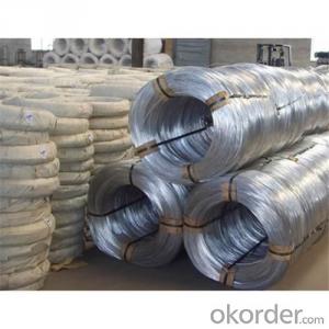
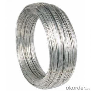
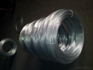
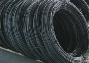
Silvery and soft binding wire
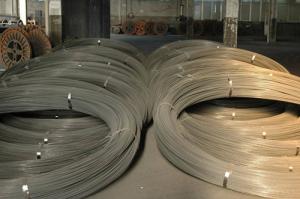
Galvanized metal wire
Material: low carbon steel
Surface treatment: galvanized
Gauge | SWG | BWG | Metric systems |
8# | 4.06 | 4.19 | 4.0 |
9# | 3.66 | 3.76 | |
10# | 3.25 | 3.40 | 3.50 |
11# | 2.95 | 3.05 | 3.00 |
12# | 2.64 | 2.77 | 2.80 |
13# | 2.34 | 2.41 | 2.50 |
14# | 2.03 | 2.11 | |
15# | 1.83 | 1.83 | 1.80 |
16# | 1.63 | 1.65 | 1.65 |
17# | 1.42 | 1.47 | 1.40 |
18# | 1.22 | 1.25 | 1.20 |
19# | 1.02 | 1.07 | 1.00 |
20# | 0.91 | 0.89 | 0.90 |
21# | 0.81 | 0.813 | 0.80 |
22# | 0.71 | 0.711 | 0.70 |
- Q: I removed my range hood (switched off the electricity for it first) and there are three wires coming out of the wall. There's a white insulated, black insulated, and totally not insulated copper wire. What is the non-insulated copper wire? When I flip the electricity on, will it have a charge? It was weirdly wrapped around a screw in the box with the wiring...I'm not sure if it was doing anything. Thanks!
- The copper wire is for ground. If there's a short, it is supposed to send the electricity into metal that leads into the soil. When you flip the switch, no charge should be in the copper wire... unless there is a short. Screw the weirdly-wrapped screw into something metal. If you have a metal utility box, screw it onto that, and you're range will be safe if there is a short.
- Q: Which wire is quot;hot, white or black?
- Usually, most Fire Alarm wiring is color-coded red and black. FPL and other fire alarm cables are usually red/black for a 2 conductor cable. If a system is wired class 1, with THHN conductors in conduit, I have seen both black and white used as the positive lead. The electricians who wire it are likely to use whatever convention they are used to. If they deal with low voltage, they could use white for + and black for -. If they are high voltage electricians, they could do the opposite. The AC service, (120V or 240V) will be wired per National Electrical Code (NFPA 70), which is black = line, white = neutral.
- Q: i want to rewire my trailer harness on my truck. i have a 6 wire roung plug but i wat a 7 wire plug. what is the 7 wires for?
- Prepare for accurate and confusing information. The center pin on a 7 pin plug is generally used for backup lights (black wire) if you have them wired in. Being that you have a 6 pin plug you probably don't so you will disregard the center pole. This is the order of color starting from the ground pole (white wire). The ground pole should be the one next to the slot in the body of the plug that lines it up with the plug housing when you put it all together. White (ground), Yellow (L turn), Brown (tail lights), Red (battery charge wire), Green (R turn), Blue (trailer brakes). If you don't have trailer brakes, disregard that pole. The brake lights work through the turn signals, if they are wired separately, it is wrong. Starting at the ground pole next to the slot in the plug, the order of colors goes around the plug in the direction away from the slot, you will end with the blue wire on the other side of the slot next to the white wire. It's very confusing to explain and when you read the colors on the plug compared to what I have told you, you will definately scratch your head. This is the (U.S.) national standard for all trailer wiring, unfortunalely, not all manufacturers adhere to this thus causing confusion for people such as yourself. I cannot even begin to guess how many trailers I have wired and how many tow packages I have installed on cars and trucks. I wish there was an easier way to explain it but the only other option is a diagram which answers does not support. Worse comes to worse and you don't like any of the other answers you get, e-mail me and I will mail you a diagram or maybe even a picture if I can come up with one.
- Q: A load of 125 kip is being held by 3 wires all going up. The Wire one goes straight from the load to the horizontal. Wire 2 and 3 form a V on top of wire 1 and are 30 degrees from wire 1. This is a 2-D problem.
- You need to use summation of forces. Wires 1 and 2 are gonna have the same tension on them, just in opposite directions. so in the x direction, Fx=125cos(30)+125cos(150) (the vertical wire doesn't contribute to the x-direction forces and I choose 150 because the wire on the left really has an angle of 180-30 or 150) in the y direction, Fy=125sin(30)+125sin(150)+125sin(90) (The vertical wire is a 90 degree angle) Tension=sqrt( Fx^2 + Fy^2 )
- Q: for christmas im getting my dad an outdoor speaker system buttheunder groung wire costs ALOT so i was wondering if regular speaker wire will work fine if i used it and burried?
- Regular speaker wire will work for a short time, but the insulation is not designed to be used underground. It will deteriorate and short out. Your other option is to use conduit, but that will probably be more expensive that the underground wire. Wire for low voltage lights will work, but the gauge is fairly small, so not much power can me pushed through the wire. There is voltage present in speaker lines, about 32-40v
- Q: The infamous headlight switch please help
- What is so infamous about plugging the wiring to the switch? It will only plug in one way. UPDATE 8/6/11: In over 45 years, I've only replaced one headlight switch that had melted and that was on a 1994 Plymouth Acclaim and the driver had left the headlights on all night and yes it drained the battery. The plastic plug had melted but the wires had not burned through, so I had something to work with. There is a possibility you can find a wiring diagram on Auto Zones website for your car, they do have an extensive library or you could try to find a Haynes manual for your car. Or if you are low on $$ if you tell us what manufacturer, model, year of car you drive someone here might be able to help.
- Q: can anyone please tell me what does hook-up wire mean and how does it differ from other kinds of wires such as light duty and heavy duty?Also,which one should I use for breadboards?
- Hookup wire is a term usually reserved for wire sizes smaller than 16 AWG, usually single strand conductor. It is generally used in applications where current-carrying capacity is not of prime importance. Breadboarding is one of these applications, but usually uses 22AWG or smaller wire.
- Q: Like I hear people say If you have good Wires you will have good bass. What is good wiring. What is the best wires I can get. Help me I'm new at this. Post some links or Something. 5 stars for best. Thanks!
- For okorder /... As for wires just for speakers 12 gage or 10the gage will work fine ..... if you have big system amp wiring is used 4 gage
- Q: Im Very Curious As To How Did The Designer Orese Make Her, African Continent Shape Wire Earrings? I Have The Supplies To Make Wire Earrings. I Would Love To Do A Personal DIY! :~)
- as well as on the first page link above, under the category Wire-Framing (P.S. Why did you use initial caps on all words in your question?...kinda hard to read.) .
- Q: how do i wire my sensor to my light
- Normally it is black wire to black wire, white to white and ground (copper) to ground.
Send your message to us
Electro Galvanized Iron Wire For Hexagonal Wire Mesh
- Ref Price:
-
- Loading Port:
- China Main Port
- Payment Terms:
- TT OR LC
- Min Order Qty:
- -
- Supply Capability:
- -
OKorder Service Pledge
Quality Product, Order Online Tracking, Timely Delivery
OKorder Financial Service
Credit Rating, Credit Services, Credit Purchasing
Similar products

Hot products


Hot Searches

