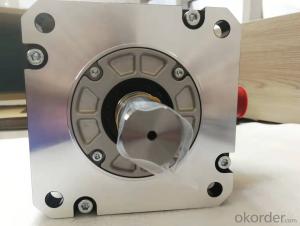
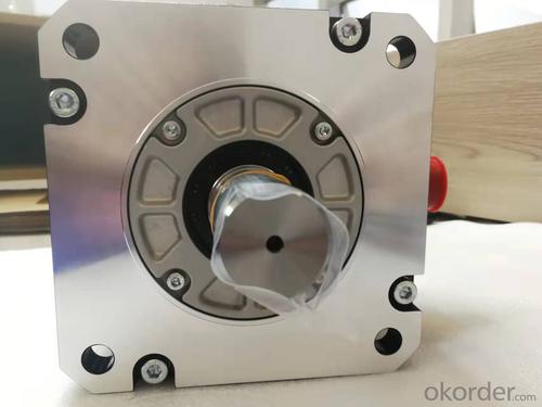
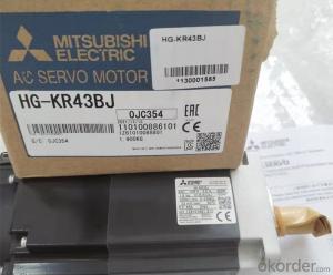
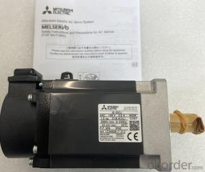
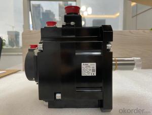
Standard Straight Shaft HG-SR352BJ Mitsubishi Motor For Injection Molding
- Loading Port:
- China main port
- Payment Terms:
- TT OR LC
- Min Order Qty:
- 1 kg
- Supply Capability:
- 1000 kg/month
OKorder Service Pledge
OKorder Financial Service
You Might Also Like
Specification
Servo motor series: low inertia, medium / high power. Rated output: 20.0kw.
Rated speed: 1000r / min. Electromagnetic brake: none.
Shaft end specification: Standard (straight shaft).
Features: there are three types of low inertia, medium and high speed models,
which are suitable for different applications. As a standard, 30kW and above
servo motors can be installed with flanges or brackets. Yiling Tongfu motor
user manual. IP grade: IP44. Application example:
1. Injection molding machine hg-sr352bj
2. Semiconductor manufacturing equipment.
3. Large material conveying system.
4. Press.
The rich motor product line can optimize the performance of the machine.
It has a rich motor product line including rotary servo motor, linear servo
motor and direct drive motor. Motor series; Medium inertia, medium power.
Rated output power: 2.0kw Mitsubishi servo motor user manual. Rated speed:
2000r / min. With or without brake: attached. Shaft end: Standard (straight
shaft). Protection level: IP65 (p67)
Features: there are three modes of medium inertia from low speed to high speed,
which are suitable for different application ranges. Application examples:
transmission machinery, robot, X-Y worktable. High resolution encoder 131072p /
rev (17 bits).
High resolution encoder is included to ensure excellent performance and
stability at low speed. Mitsubishi Tongfu motor user manual. All motors are the
same size as the previous products and the wiring is compatible. Motor series:
flat type, medium and small power. Rated output power: 1.5kw. Rated speed:
2000r / min. with brake or not: attached. Shaft end: Standard (straight shaft).
Protection level: p65 (p67)
Features: the flat design makes this model more suitable for installation in a
narrow space. Hg-sr352bj user manual. Application examples: robots, food
manufacturing machinery.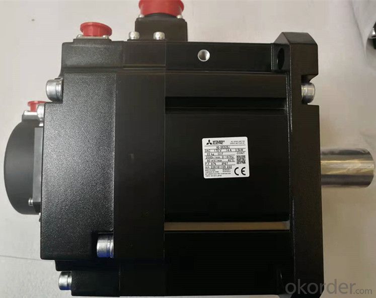
High resolution encoder 131072p / rev (17 bits).
High resolution encoder is included to ensure excellent performance and
stability at low speed. All motors are the same size as the previous products
and the wiring is compatible. Motor: ha-uh type, power: 4.5kw.
Speed: 2000r / min
According to the type of working power supply: it can be divided into DC motor
and AC motor hg-sr352bj user manual. DC motor can be divided into brushless DC
motor and brushless DC motor according to structure and working principle..
Brushless DC motor can be divided into permanent magnet DC motor and
electromagnetic DC motor.
Division of electromagnetic DC motor: series excited DC motor, parallel excited
DC motor, separately excited DC motor and compound excited DC motor Hg sr352bj
user manual.
Permanent magnet DC motor is divided into rare earth permanent magnet DC motor,
ferrite permanent magnet DC motor and aluminum nickel cobalt permanent magnet
DC motor. Type: hc-pq type
Output power: 0.4KW. Rated speed: 3000r / min. electromagnetic braking: none.
Key axis: straight axis.
In terms of motor: the material, structure and processing technology of servo
motor are much higher than that of AC motor driven by frequency converter, that
is, when the driver outputs the power supply with rapid changes in current,
voltage and frequency, the same server motor can produce response action
changes according to the changes of power supply.
The response characteristics and anti overload ability are much higher than
those of AC motor driven by frequency converter.
The serious difference in motor is also the fundamental reason for the
different performance of the two. Hg-sr352bj manual. That is to say, it's not
that the frequency converter can't output the power signal that changes so
fast, but that the motor itself can't respond,
Therefore, when setting the internal algorithm of frequency conversion, in
order to protect the motor, the corresponding overload setting is made in the
user manual of Mitsubishi servo motor. Of course, even if the output capacity
of the frequency converter is not set, it is still limited. Some frequency
converters with excellent performance can directly drive the servo motor.
- Q: I am powering a lighting system with a mixture of SCR dimmers and HID lamps. I am pulling approx 285 amps/leg at 120/208V through a 150 kVA transformer. The 120/208V service coming from that transformer is indicated to be 400A/leg, but it seems to get pretty hot at 285A.
- Three phase transformers are given a power rating which is the sum of all three powers on each phase. So 285 amps on each phase at 120 line to neutral (assuming this is how youve them connected) is about 35kva, so about 100kva all up. What is actually on the name plate of the transformer? How hot is 'pretty hot'? Is it running as it was desinged (oil, dry, forced air cooling etc). Also how are your lamps/dimmers wired? The other answer is correct, the dimmers will produce alot of harmonics. The meter your are using to read the current is most likely designed to read a 60hz sine wave, any other stuff there will cause a wrong reading (they usually measure the average value, then apply a correction factor to obtain the rms value. But this factor depends on the wave shape, if its not a sine wave it will be wrong). See if you can obtain a meter that will measure the true RMS current. Transformers of that size are usually heavily over engineered, it should be fine as long as the tempertature doesnt continue to increase, ie to the point where the case is too hot to touch. As the other answer said it is probably rated for continuous operation at about 75 degrees. Id not worry too much as long as the temperature doesnt continue increasing.
- Q: Go transformers
- Neither. Pirates 3 was way better than Spider man 3, and I haven't seen Transformers so I can't pick it.
- Q: How many times does a copper wire have to go around the input side of a transformer to get the necessary amount of magnetism from 110 volts?How thick does the wire around the transformer have to be if the input it 110 volts? Can it be one wire as thin as a garbage bag tie, or does it need to be as thick as the original wire, but stripped and coiled around the transformer core?
- As stated in another answer, the basic transformer equation is: E 4.44 X f X N X Ac X B E is the applied RMS voltage f is the frequency (Hz) N is the number of turns Ac is the core area (square meters) B is the maximum flux density (Webers per square meter also kknown as Teslas) If the design is for 120 volts at 60 Hz and 1 Tesla, the required number of turns would be about 0.5 divided by the core area. PS The voltage has nothing to do with the thickness of the wire. Wire thickness is determined by current, the desired internal voltage drop in the wire resistance and the tolerable temperature due to internal losses. Magnet wire is used. It has very thin insulation to use the minimum space and allow heat to be more easily conducted out of the coil. The wire can not be stripped bare.
- Q: Production of high and low voltage switchgear transformer industry belongs to what industry category
- Category C Manufacturing Electrical machinery and equipment manufacturing In the class 392 transmission and distribution and control equipment manufacturing
- Q: I'm a student in high school in a basic physics class. My teacher assigned a report and presentation about electric transformers(because its not in our textbooks), but the information i get from websites is too complicated for me to understand.(ie wikipedia) Is there a website where i can get thorough info that is easy to understand?
- $20 at most big electronics retailers, within 500 watts larger transformers can be up to $100 to 2000 watts.
- Q: 50KVA transformer each phase current maximum band
- Normal current does not exceed 72A per phase current. Of course, in the event of an accident or to strengthen the transformer cooling can be short-term overload operation.
- Q: I have a few power tools, none of which are natively wired for 110-240v. In particular, a portable table saw, a router, and a mitre saw, all at 220v. Since the resale value of them are so low on auction sites, I was thinking of taking them with me when I shift home to the states. Would it be safe using those tools, for extended periods, whilst running them on a transformer?
- You can do that. Just make sure the transformer is rated for the power they will draw. Keep this in mind: American homes are wired with 220 volts. Only, they split the voltage into two 110 volt legs. Each leg to ground (or neutral) is 110 volts (also commonly referred to as 120 volts). But from one leg to the other is where you get the 220 (or 240) volts. My garage is wired with two legs of 110, which means I have 220 out there. I also have an outlet for 220 volts. Because some of the power tools I run demand more current, and run them simultaneously, the standard 110 outlets struggle to meet the demand. So what I did was to take a dryer cord and wire it into a pony panel where I can draw 110 volts from one leg to ground to power a table saw while the other leg powers the dust collection system. To try and run both those pieces of equipment on a single 110 line means a trip to the breaker to reset it because each draws enough power that when used together they draw more current than the circuit is safely rated for. YOU can do something similar. Just make sure you use a 20 amp outlet meant for use with 220 volts and wire into the panel (if not already wired) and set up a 220 volt plug where you will be using these power tools. Using a transformer will work, but the more you couple the power magnetically the more inefficient your system becomes, and you waste power. Also consider just buying tools rated at 110 volts. They're plentiful and cheap enough that the cost may offset the cost of shipping these 220 v tools. Throw in the cost of a transformer and you're probably spending more money in the long run. Hope this helps. '')
- Q: i would say transformers alll the way
- They were both pretty bad but I'd go with Transformers since it actually seemed to have a plot and awesome effects.
- Q: Can a european power outlet handle a 5000 watt power transformer?
- A Power Transformer is usually rated in KVA, or Killo-Volt Amps. Hard to answer your question without the right info on the size of the X-fmr, What it is being used for, and the number of taps on said X-fmr. An appliance that consumes 5K Watts of power can be translated to about 7 Amps @ about 100 to 120 Volts A.C. It can also be translated to about 3.5 Amps @ 200 to 240 Volts A.C. I like to over rate things in my calculations, for safety sake. That way, there are no accidents in adding up figures wich could possibly cause a circuit overload. Frequency of the line doesn't really matter, unless you are converting power for an imported or domestic unit, whatever the case may be. Consult your local friendly electrician for other details.
- Q: Do you think transformers is a good movie?Whos your favourite team autobots or decepticons?Whos your favourite transformer?And whats the best scene in the film?
- Not bad.My brother is intersted in it very much.
Send your message to us
Standard Straight Shaft HG-SR352BJ Mitsubishi Motor For Injection Molding
- Loading Port:
- China main port
- Payment Terms:
- TT OR LC
- Min Order Qty:
- 1 kg
- Supply Capability:
- 1000 kg/month
OKorder Service Pledge
OKorder Financial Service
Similar products
Hot products
Hot Searches
