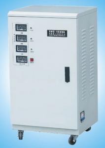
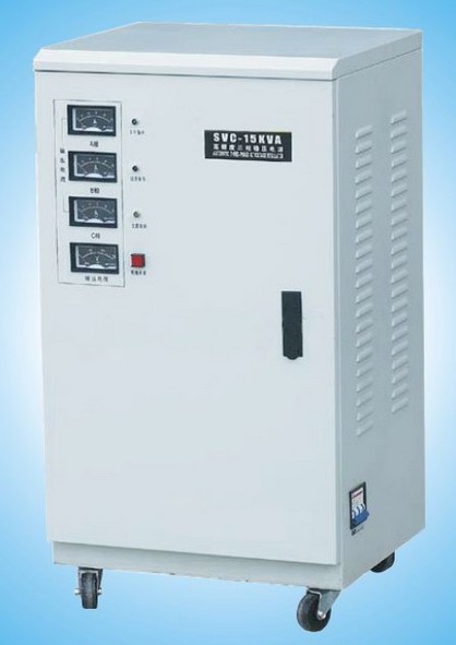
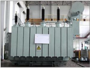
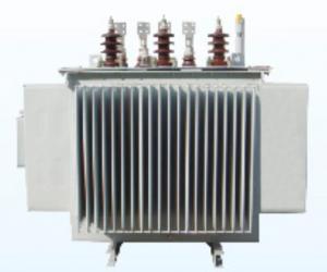
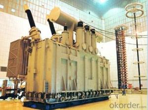
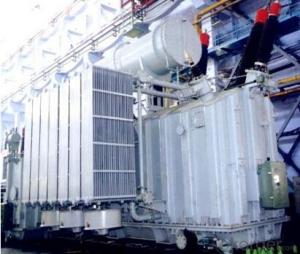
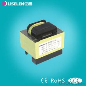
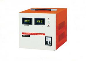
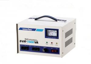
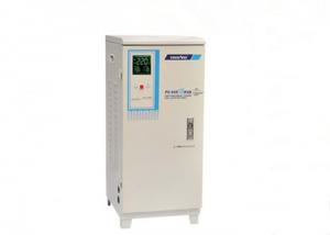
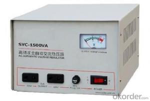
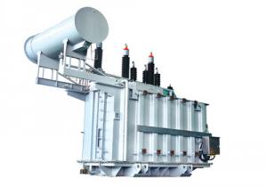
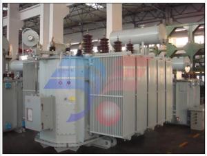
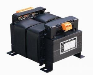
SAR Series Fully Automatic A.C.Voltage Regulator
- Loading Port:
- Shanghai
- Payment Terms:
- TT OR LC
- Min Order Qty:
- -
- Supply Capability:
- 10000pcs pc/month
OKorder Service Pledge
OKorder Financial Service
You Might Also Like
1.Application
These special products of SAR series Voltage Regulator have advanced equipment, abundant technology, reliable quality and distinguished credit. SAR series are designed at JS3717-84 request, these products conform to fully automatic control of integrated circuit. They are of quick speed, good reliable of sensitive action, convenient use and assure the stale resuit. They are suitable for families, schools, enterprises, hotels and diets etc., where need a stable civil power. They can make the illumination lamp, TV set, air-conditioner, refrigerator, computer SAR-2000VA and copy machine etc. work at a normal condition and have a long using time.
2. Technical specification
| Frequency | Regulating Time | Temperature Rise | Withstand Voltage | Low Voltage Protection | Over Voltage Protection |
|---|---|---|---|---|---|
| 50-60Hz | Less Than 0.5 | <60oC | Accord With Ministry Issued Standard | Output 100V/160V | Output 270V/260V |
| Model | Range | Input Civil Power Voltage(V) | Output Precision of Stabling Voltage | ||
| Current | 160-260 | 220V±5% | |||
| 0.5KVA To 5KVA | Over-Low Voltage | 130-270 | 220V±8% | ||
| Special Over-Low Voltage | 100-270 | 220V±10% | |||
| High Precision of Stabling Voltage | 160-270 | 220V±3% | |||
- Q: Transformer voltage ratio and current ratio.
- On the transformer voltage ratio and current ratio formula Turn left to turn right E1 is the original coil in the electromotive force, want to U1 is the back electromotive force. E2 is the electromotive force in the secondary coil, relative to U2 is the power supply. △ Φ1 is the magnetic flux through the original coil, is through the secondary coil in the magnetic flux. R1, r2 are the primary secondary coil resistance. Turn left to turn right If not the magnetic loss △ Φ1 = △ Φ2 There is Turn left to turn right According to Ohm's Law Turn left to turn right If the wire resistance is not counted, there are Turn left to turn right If the eddy current loss of the core is not counted, the input power of the transformer is equal to the output power This is available
- Q: hey Guys. I'm a big fan of Transformer movies. can't wait to see the Transformers-2. Not a real trailer has been released? :( . I would like to know which robots r going to b in the next epic battle?? :)
- Soundwave. Optimus Prime 3
- Q: I have a question can someone explain why transformers get hot in use and why must they not be allowed to get too hot
- Transformers are two separate coils of wire wrapped together around a core. The wires are not connected to each other Electricity flowing through one coil induces a currant in the other. When you are using a device connected to the transformer electricity has to pass from one coil to the other. This action does create heat. If the transformer gets too hot the insulation between the coils of wire will melt and short the circut. Some times they do catch fire. just a simplified explanation.
- Q: I have a transformer which I got from a alarm system and wondered if I can use it in conjunction with my newly purchased bread board.I don't know how I would tell what the transformer is, I'm assuming the input is 230v (UK) but the output I'm not sure. The resistances of the windings are 0.7 ohms and 74 ohms. I'm assuming the output will be around 23V? Also, if I was to use this, which winding would the mains connect to, the lower resistance or higher resistance?
- Not okorder
- Q: What are the technical parameters of the transformer?
- C, rated current (A): transformer in the rated capacity, allowing long-term through the current. D, no load loss (kW): when the rated frequency of the rated voltage applied to the end of a winding, the other winding open when the active power. And the core silicon steel sheet performance and manufacturing process, and the applied voltage. E, no-load current (%): When the transformer in the rated voltage under the secondary side of the load, the current through a winding, generally expressed as a percentage of the rated current. F, load loss (kW): the transformer secondary winding short circuit, in a winding rated tap position into the rated current, then the power consumption of the transformer. G, the impedance voltage (%): the secondary winding of the transformer short circuit, in a winding slowly increase the voltage, when the secondary winding short-circuit current equal to the rated value, then the voltage applied once the general. As a percentage. H, the number of phases and frequency: three-phase beginning to S said, single-phase start with D said. China's national standard frequency f is 50Hz. Foreign countries have 60Hz (such as the United States).
- Q: I want to know how much the current will increase. But the transformers i'm looking at VCT VT10000 - 10,000 Watts Heavy Duty Continuous Use 110V / 220V / 240V Step Up / Step Down Voltage Transformer or 15,000 Watt Step Up and Step Down Voltage TransformerI figure the whats is the total possible power and if you divide the power by the intial voltage you get the current and if you divide by the out put voltage you get the final current? but what if you input doesn't equal 15000 watts or whatever the power is?
- The rating of a transformer like this one is really in volt amps, not watts. This is because the winding losses are proportional to the RMS current squared. If the load current is not in phase with the voltage, the power is voltage times current times the power factor which will be less than V*I.
- Q: This transformer outputs AC or DC
- If you have 220V output voltage, then the peak voltage of the waveform is 220 * 1.414 = 311v, then your rectifier at least reverse voltage of not less than 400V, then the voltage is not more than 400V The Look at your transformer current, if the full load current is 7A, then your rectifier load capacity should not be less than 10A. So the main consideration is the rectifier voltage and current these two aspects.
- Q: I understand US voltage appliances use 2 x 110v hot leads to make 220v @ 60 Hz. The voltage in China is 220v @ 50 Hz. Would I have to get 2 step down transformers to make 2 x 110v hot leads? I found transformers making 220v @ 50 Hz to 110v @ 60 Hz, but only one lead. How can I make it work over there? I understand there are ranges at 220v made specifically for Europe and China at 220v, but I love this range. I want to use this range made for the US in China. What would be the way to do this? Any help would be grreatly appreciated!
- First off a killer range better than one you have ever had can be purchased in China for the price of the transformers needed to make that one work. Put it in storage till you come back. But if you must take it your range will need two step down transformers sized in VA correctly for that load. You cannot plug them both into the same receptacle and get it working they will have to be on two separate circuits so that means running an extension cord from across the room to power the other leg. The voltage is the same phase over there so you need two hots and two grounds from two separate circuits then rigged into a receptacle for it to plug into and it still may not work. Your stove has to be rated for 50 and 60 hertz or the timer clock and any other gauges wont work at all or will get messed up. Be safe and buy a new one. The transformers work great for small appliances and are not designed to do what you want. When over there be sure to buy all dual voltage electronic items so you can bring them back to the U.S. and just flip a switch and they will run great. I hope this helps.
- Q: 630kva dry-type transformer rated current is how much
- Hello there: - ★ 1, the transformer current calculation formula is: transformer capacity ÷ (rated voltage × root number 3) - ★ 2,630kva transformer primary current: 630kva ÷ (10kv × 1.732) = 36.37A; - ★ 3,630kva transformer secondary current is: 630kva ÷ (0.4kv × 1.732) = 909A.
- Q: How is the insulation of the transformer divided?
- Insulation can be divided into two parts: main insulation and vertical insulation. The main insulation is between the winding and the ground part, and the insulation between the windings.
Send your message to us
SAR Series Fully Automatic A.C.Voltage Regulator
- Loading Port:
- Shanghai
- Payment Terms:
- TT OR LC
- Min Order Qty:
- -
- Supply Capability:
- 10000pcs pc/month
OKorder Service Pledge
OKorder Financial Service
Similar products
Hot products
Hot Searches
