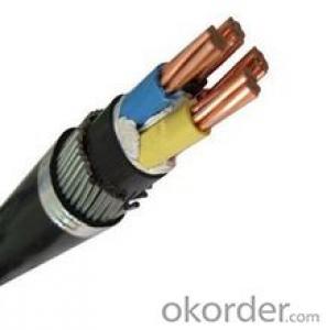
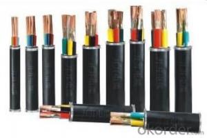
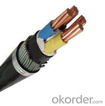
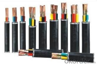
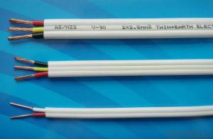
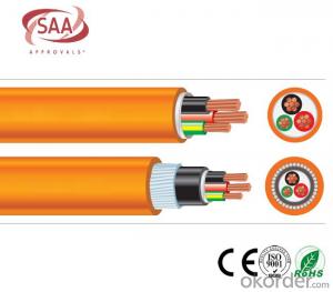
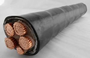
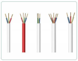
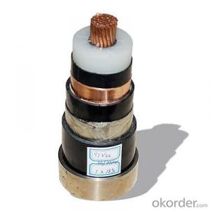
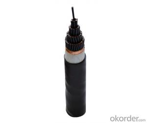
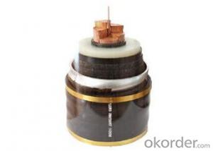
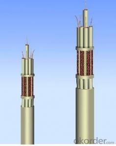
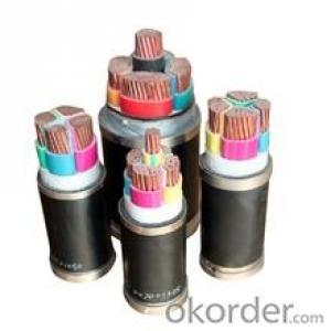
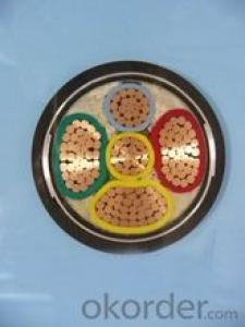
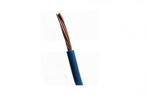
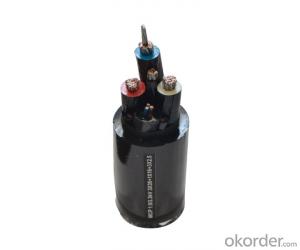
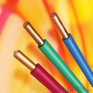
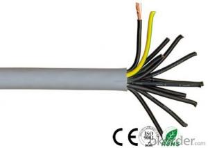
PVC insulated PVC / XLPE sheathed cable
- Loading Port:
- China main port
- Payment Terms:
- TT OR LC
- Min Order Qty:
- 100 m
- Supply Capability:
- 20000 m/month
OKorder Service Pledge
OKorder Financial Service
You Might Also Like
1.Basic information:
U0/U: 450/1000V
Max working temp: 70℃
Conductor: Class 1/2 plain copper wires, solid or strand
Insulation: Out ring: PVC, inner ring: PVC or XLPE
Section area: 7.5-240mm2
Package: Steel-wooden drum, length on the size or your demand
Certification: ISO9001:2008, CE, RohS, CCC
Samples: we can supply samples free of charge, but the buyer should pay the freight cost.
Products list of the factory
PVC insulated PVC/XLPE sheathed copper cables (Lower than 1000 Voltage) | |||
No. | Size | Specification | Weight/m |
21 | 3×2.5 mm2 | 3×1.78 mm2 | 0.193kg |
22 | 3×4 mm2 | 3×2.25 mm2 | 0.27kg |
23 | 3×4+1×2.5 mm2 | 3×2.25+1×1.78 mm2 | 0.3kg |
24 | 3×4+2×2.5 mm2 | 3×2.25+2×1.78 mm2 | 0.325kg |
25 | 3×6 mm2 | 3×2.76 mm2 | 0.34kg |
26 | 3×6+1×4 mm2 | 3×2.76+1×2.25 mm2 | 0.391kg |
27 | 3×6+2×4 mm2 | 3×2.76+2×2.25 mm2 | 0.47kg |
28 | 3×10 mm2 | 3×7×1.35 mm2 | 0.51kg |
29 | 3×10+1×6 mm2 | 3×7×1.35+1×2.76 mm2 | 0.574 |
30 | 3×10+2×6 mm2 | 3×7×1.35+2×2.76 mm2 | 0.681kg |
31 | 3×16 mm2 | 3×7×1.70 mm2 | 0.717kg |
32 | 3×16+1×10 mm2 | 3×7×1.70+1×7×1.35 mm2 | 0.856kg |
33 | 3×16+2×10 mm2 | 3×7×1.70+2×7×1.35 mm2 | 1.04kg |
34 | 3×25+1×16 mm2 | 3×7×2.14+1×7×1.70 mm2 | 1.224kg |
35 | 3×25+2×16 mm2 | 3×7×2.14+2×7×1.70 mm2 | 1.436kg |
36 | 3×35+1×16 mm2 | 3×7×2.52+1×7×1.70 mm2 | 1.478kg |
37 | 3×35+2×16 mm2 | 3×7×2.52+2×7×1.70 mm2 | 1.757kg |
38 | 3×50+1×25 mm2 | 3×10×2.52+1×7×2.14 mm2 | 2.081kg |
39 | 3×50+2×25 mm2 | 3×10×2.52+2×7×2.14 mm2 | 2.415kg |
40 | 3×70+1×35 mm2 | 3×14×2.52+1×7×2.52 mm2 | 2.796kg |
41 | 3×70+2×35 mm2 | 3×14×2.52+2×7×2.52 mm2 | 3.357kg |
42 | 3×95+1×50 mm2 | 3×19×2.52+1×10×2.52 mm2 | 3.81kg |
43 | 3×95+2×50 mm2 | 3×19×2.52+2×10×2.52 mm2 | 4.535kg |
44 | 3×120+1×70 mm2 | 3×24×2.52+1×14×2.52 mm2 | 4.782kg |
45 | 3×120+2×70 mm2 | 3×24×2.52+2×14×2.52 mm2 | 5.716kg |
46 | 3×150+1×70 mm2 | 3×30×2.52+1×14×2.52 mm2 | 5.743kg |
47 | 3×150+2×70 mm2 | 3×30×2.52+2×14×2.52 mm2 | 6.791kg |
48 | 3×185+1×95 mm2 | 3×37×2.52+1×19×2.52 mm2 | 7.157kg |
49 | 3×185+2×95 mm2 | 3×37×2.52+2×19×2.52 mm2 | 8.489kg |
50 | 3×240+1×120mm2 | 3×48×2.52+1×24×2.52mm2 | 9.158kg |
51 | 3×240+2×120mm2 | 3×48×2.52+2×24×2.52mm2 | 10.813kg |
52 | 4×2.5 mm2 | 4×1.78 mm2 | 0.236kg |
53 | 4×4 mm2 | 4×2.25 mm2 | 0.327kg |
54 | 4×4+1×2.5 mm2 | 4×2.25+1×1.78 mm2 | 0.366kg |
55 | 4×6 mm2 | 4×2.76 mm2 | 0.421kg |
56 | 4×6+1×4 mm2 | 4×2.76+1×2.25 mm2 | 0.474kg |
57 | 4×10 mm2 | 4×7×1.35 mm2 | 0.64kg |
58 | 4×10+1×6 mm2 | 4×7×1.35+1×2.76 mm2 | 0.735kg |
59 | 4×16 mm2 | 4×7×1.70 mm2 | 0.909kg |
60 | 4×16+1×10 mm2 | 4×7×1.70+1×7×1.35 mm2 | 1.052kg |
61 | 4×25 mm2 | 4×7×2.14 mm2 | 1.302kg |
62 | 4×25+1×16 mm2 | 4×7×2.14+1×7×1.70 mm2 | 1.565kg |
63 | 4×35 mm2 | 4×7×2.52 mm2 | 1.738kg |
64 | 4×35+1×16 mm2 | 4×7×2.52+1×7×1.70 mm2 | 1.966kg |
65 | 4×50 mm2 | 4×10×2.52 mm2 | 2.421kg |
66 | 4×50+1×25 mm2 | 4×10×2.52+1×7×2.14 mm2 | 2.768kg |
67 | 4×70 mm2 | 4×14×2.52 mm2 | 3.298kg |
68 | 4×70+1×35 mm2 | 4×14×2.52+1×7×2.52 mm2 | 3.751kg |
69 | 4×95 mm2 | 4×19×2.52 mm2 | 4.394kg |
70 | 4×95+1×50 mm2 | 4×19×2.52+1×10×2.52 mm2 | 5.016kg |
71 | 4×120 mm2 | 4×24×2.52 mm2 | 5.452kg |
72 | 4×120+1×70 mm2 | 4×24×2.52+1×14×2.52 mm2 | 6.277kg |
73 | 4×150 mm2 | 4×30×2.52 mm2 | 6.772kg |
74 | 4×150+1×70 mm2 | 4×30×2.52+1×14×2.52 mm2 | 7.535kg |
75 | 4×185 mm2 | 4×37×2.52 mm2 | 8.139kg |
76 | 4×185+1×95 mm2 | 4×37×2.52+1×19×2.52 mm2 | 9.36kg |
77 | 4×240 mm2 | 4×37×2.52 mm2 | 10.611kg |
78 | 4×240+1×120 mm2 | 4×48×2.52+1×24×2.52mm2 | 11.896kg |
79 | 5×2.5 mm2 | 5×1.78 mm2 | 0.287kg |
80 | 5×4 mm2 | 5×2.25 mm2 | 0.401kg |
81 | 5×6 mm2 | 5×2.76 mm2 | 0.517kg |
82 | 5×10 mm2 | 5×7×1.35 mm2 | 0.774kg |
83 | 5×16 mm2 | 5×7×1.70 mm2 | 1.105kg |
84 | 5×25 mm2 | 5×7×2.14 mm2 | 1.648kg |
85 | 5×35 mm2 | 5×7×2.52 mm2 | 2.141kg |
86 | 5×50 mm2 | 5×10×2.52 mm2 | 2.997kg |
87 | 5×70 mm2 | 5×14×2.52 mm2 | 4.071kg |
88 | 5×95 mm2 | 5×19×2.52 mm2 | 5.247kg |
89 | 5×120 mm2 | 5×24×2.52 mm2 | 6.734kg |
90 | 5×150 mm2 | 5×30×2.52 mm2 | 8.383kg |
91 | 5×185 mm2 | 5×37×2.52 mm2 | 10.288kg |
92 | 5×240 mm2 | 5×48×2.52 mm2 | 13.201kg |
- Q: The name of the plastic rope of the wire when the computer is installed
- You better do not change! The Because the line if the wrong will really burn the motherboard or USB device! The Is it not a 5m USB extension cord? You can buy one! The Or with two 3-meter pick up! It can be! The Too long a USB cable will affect the signal transmission! I suggest you do not exceed 5 meters (5 meters has been very metamorphosis)! The hope this helps! The The
- Q: I understand how to connect wires together. Black to black and white to white. I have done several electrical jobs in my own home with success. However I am trying to connect my range hood to a main power supply and have been unsuccessful several times. I don't know what I'm doing wrong. In fact, I have undercabinet lights run to the same power supply and they work just fine. I know I am not overloading because I have even disconnected my lights and just tried the range hood. Any advice?
- My advice is call an electrician. Nothing in a home is easier than a hood if that is giving you trouble then you are unqualified to be working with electricity. As far as the other job you have successfully done , just because it works doesn't me you did it right it could be a fire or accident waiting to happen. It is very arrogant to think you could learn to do something like the wiring in your home. Most states agree to learn to wire safety takes four years of on the job training and four years of school.
- Q: going to roll out attic insulation between the ceiling joists. what do I do when I come across wires that go through the joists? Can I roll the insulation over the wires or should I cut it and leave the wire exposed and start the roll again on the other side of the wire?
- The best way is to cut the insulation a foot longer than the distance to the wire, then split the insulation so that it goes above and below the wire. Start a new piece of insulation tucked tight to the last. If you fill up the bays, and you could use more insulation go at right angle to the first layer.more is better
- Q: i under the house. Does that mean I will need to have the house rewired
- Most likely.
- Q: I have a module panel which is suppose to transfer dc to ac electric. Is the wires soldered on the back of the panel or any metal on the sides? What colors are the wires?
- Guide okorder
- Q: I am prepping it for a derby and accidentally cut the fuel pumps electrical wire harness thinking it was stereo or tail lights. I just want to hook it up to start it and move it to the shop where i can really tear into it. There are 4 wires. Black, purple, grey, and black w/ yellow stripe. I want to bypass the electrical connectors and just splice it into the wires that run along the drivers side floor. What color wire is what and what color do i splice it to?
- you will would desire to make certain in case you have potential and floor to the gas pump. regrettably you will would desire to drag the tank off to make certain the relationship. The helpful cord from the relay is a grey cord. the floor cord is a robust black cord. you are able to connect a attempt mild between the two terminals and turn on the significant. the sunshine could come on for extra or less 2 seconds and then pass off. Or in case you're cranking the engine, the attempt mild could be on once you're cranking. No mild,then you definately've a potential or floor concern. mild on, then you definately probable have a dud gas pump.
- Q: I am also concerned that the electrical wires have been stapled down with metal staples, can the heat burn through the wire insulation and short out the wires? Last year I was in the attic on a hot day and the wires were almost too hot to touch. I've installed ventilation this year and I want to find a target temp, it's common for the temperature outside to be in the 90s where I live.
- Don't worry about the wires. The wire coating will sustain temps up in the 400 degree range. I recently installed (2) powered roof vent fans on a roof for a customer. These fans actually suck out the hot attic air and bring in cooler air from the soffit vents. If you just installed gravity type roof vents you may want to add a power attic fan. Just remember you need a source for air to come into the attic. Ridge vent is almost worthless as it does constrict the air flow - I am not a big fan of Ridge vent. Hip roofs are harder to vent as there are no gables which means most of the hot attic air is trapped on the hip sides as there is not even a place for ridge vent except for a small portion of the top ridge board.
- Q: I am getting quotes for installing a Guardian back generator. One contractor wants to charge almost $1200.00 to extend the electric wire 68' across the basement to the circuit box. I know this wire is very cheap, and I've paid electricians about $90 per hour in the past. A task like this should take a pro no more than an hour to do. I feel they are trying to cheat me.
- $1200 seems high. Wire is not cheap anymore due to high copper prices, but that type of wire shouldn't be more than $1-2 per foot. Even with a circuit breaker and other stuff, his cost can't be more than $200. That leaves a heck of a profit for an hour or two of work.
- Q: I am putting all my lighting on a single circuit, and have a question. The main feed from the panel to the lights first goes to a double gang switch, one switch controls the lights on half of the main room in the basement, the other controls the lights in the other half of the main room in the basement. Then I need the main feed to continue to three other switches in three other rooms in the basement. Do I just wire nut the black wired and wire nut the white wires, and continue running to the next switch. So if that is the case, then am I correct in saying that in the double gang switch I will have one wire nut with the ground wires, one wire nut with 4 black wires, and one wire nut with 4 white wires? Please help with this matter, I want to do this correct, so my house doesn't burn down.By the way I am using 14/2 wire.
- Yes,this will work. The rule of thumb is to break the Black for lights and switches, and to keep the white wire pure (contiuous). I hope this helps. I know that wiring can get confusing trying to wire in more than one switch on a line, so good luck.
- Q: i have tail lights and a right hand turn signal,there is juice getting through the wires. but i have no brake lights. it is a 83 olds. where do i look, or how do i solve this?
- Does the turn signals work on both sides? If no, wiring, bulbs, turn signal switch. If they work fine, bad switch on the pedal or no power to the pedal switch. How to tell one fuse from another, you are going to need a drawing. The dealer can print one off, but they might want a little money.
Send your message to us
PVC insulated PVC / XLPE sheathed cable
- Loading Port:
- China main port
- Payment Terms:
- TT OR LC
- Min Order Qty:
- 100 m
- Supply Capability:
- 20000 m/month
OKorder Service Pledge
OKorder Financial Service
Similar products
Hot products
Hot Searches
