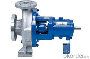

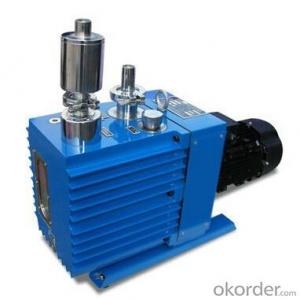
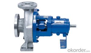
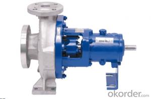
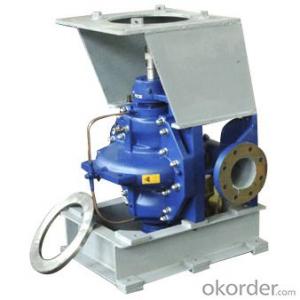
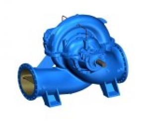
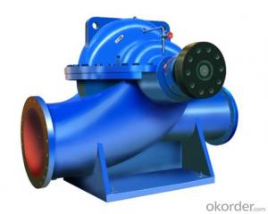
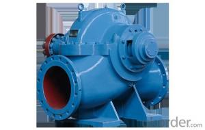
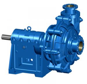
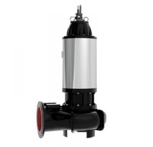
Horizontal, radially split, single-stage volute casing pump CPK-D
- Ref Price:
-

- Loading Port:
- Shanghai
- Payment Terms:
- TT OR LC
- Min Order Qty:
- 1 pc
- Supply Capability:
- 1 pc/month
OKorder Service Pledge
OKorder Financial Service
You Might Also Like
Design |
Overview of technical data
| Type of impeller | Radial; Closed;Multi-vane impeller |
| Type of installation | Long- coupled |
| Maximum drive rating | 220 kW |
| Diffuser material (EN standard) | JL 1040; NORIDUR 1.4593;1.4408 |
| Impeller material (EN standard) | 1. 4408;JL 1040;NORIDUR 1.4593 |
| Type of bearing | Rolling element bearings |
| Drive frequency | 50 Hz / 60 Hz |
| Maximum speed of rotation | 3. 500 1/min |
| Maximum flow rate | 1. 250 m³/h |
| Maximum discharge-side pressure | 25 bar |
| Casing material (EN standard) | JS 1025; 1.4408;NORIDUR 1.4593 |
| No. of impeller entries | Single entry |
| Casing material | Cast duplex steel; Cast stainless steel;Special KSB material;Nodular cast iron |
| Minimum flow rate | 2 m³/h |
| Suction characteristics | Non- priming |
| Drive voltage | Low voltage |
| eClass assignment | 36410101; 36410100;36410000 |
| Pull-out design | Yes |
| Pump set location | Dry installed |
| Max. permissible fluid temperature | 150 ****** |
| Main applications | Industry and process engineering; Energy |
| Type of installation | Stationary |
| Type of casing | Volute casing |
| Type of lubrication | Oil lubrication |
| Type of drive | Electric motor |
| Installation position | Horizontal |
| Shaft material (EN standard) | C 45+ N |
| Type of coupling | Direct |
| Shaft seal type | Hydrodynamic seal |
| Maximum head | 220, 00 m |
| Maximum rated pressure (discharge) | PN 25 |
| Minimum head | 9, 00 m |
| Nozzle position | End suction |
| Casing partition | Radially split |
Private customers
Looking for information about products, services, and spare parts? All information is provided here along with the details of your contact person.
Find out moreLegal help
© KSB Aktiengesellschaft
- Q: What are the internal losses in centrifugal pumps? How did they come about?
- Hydraulic loss: the loss of water by friction, eddy, impact, etc in a flow;
- Q: What is a gear pump for?
- Oil pump casing wearIt is mainly the wear of the floating sleeve hole (the normal clearance between the gear shaft and shaft sleeve is 0.09~0.175mm, and the maximum shall not exceed 0.20mm). The gear work is affected by the pressure oil, the gear tip is close to the oil pump casing, and the low pressure chamber part of the pump body is worn. Another kind of wear is the circumferential wear of the work surface in the shell. This kind of wear is mainly caused by the addition of oil which is not clear, so the oil without impurities is necessary.
- Q: What are the reasons for sealing damage of centrifugal pumps?
- The reasons for sealing damage of centrifugal pumps are as follows: six, the specific contents and handling methods are as follows:First, the centrifugal pump water quality is poor, containing particles.As a result of poor water quality, containing small particles and medium hydrochloride content is high, forming abrasive wear, centrifugal pump seal plane or pull the surface, resulting in groove, ring groove and so on.Treatment method: improve water pressure or medium, replace machine seal.
- Q: Why can the centrifugal pump hold down the pressure?
- The centrifugal pump can hold pressure because of the suction pipe in the pump at the entrance of a non-return valve (valve).
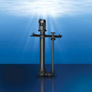
- Q: What are the characteristics of a vertical multistage centrifugal pump?
- A liquid that is primarily diluted, clean, non corrosive, explosive, or similar to water but contains no solid particles or fibers. Because of its high flow and large lift, it is widely used in fire fighting, water supply and air conditioning unit cooling water transportation in high-rise buildings.
- Q: Difference between pump and compressor
- In the spiral case, the liquid slows down due to the gradual enlargement of the flow passage, and the part of kinetic energy is converted to static pressure, and finally flows into the exhaust pipe at higher pressure and is sent to the required place. When the liquid flows from the center of the impeller to the outer edge, a vacuum is formed at the center of the impeller. As the pressure at the upper level of the tank is greater than the pressure at the pump inlet, the liquid is continuously pressed into the impeller. Visible, as long as the impeller continues to rotate, the liquid will continue to be inhaled and discharged.The working principle of the linear pump is different from that of any other pump. It adopts the principle of magnetic suspension and the hydraulic structure of the spiral ring to realize liquid propulsion, that is, to cancel the shaft, to cancel the shaft connection, and to cancel the sealing structure of the shaft. After starting, the electric current is transformed into a magnetic field, and the magnetic field force drives the spiral ring to move, namely, the spiral ring promotes the liquid advance.Compressor (compressor), a driven fluid machine that promotes low-pressure gas as a high pressure gas, is the heart of a refrigeration system. It is of low temperature and low pressure refrigerant gas suction pipe from the suction, through the operation of the motor drives the piston to compress it after high temperature and high pressure refrigerant gas discharge pipe to the exhaust, to provide power for the refrigeration cycle, so as to realize the compression and condensation (exothermic), expansion and evaporation (endothermic) refrigeration cycle.
- Q: Working principle and structure of external gear pump
- External gear pump is the most widely used gear pump, the general gear pump usually refers to the external gear pump. Its structure as shown in the diagram, there are mainly driving gear, driven gear, pump body, pump cover and safety valve and so on. The seal space of pump body, pump cover and gear is the workshop of gear pump. The wheel shafts of the two gears are respectively arranged in the bearing holes on the two pump cover, and the driving gear shaft extends out of the pump body and is driven by the motor to rotate. The external gear pump is simple in structure, light in weight, low in cost, reliable in operation and wide in application. When the gear pump works, the driving wheel rotates with the motor and drives the driven wheel to rotate
- Q: If the calculation of the required pump flow is 45, lift 110, and the actual pump flow 100, head 125, what will happen in operation? Can I use it properly?
- First of all, the performance curve of the centrifugal pump is similar to the track of the train, and the train can not run away from the track.Secondly, the performance curves of centrifugal pump mainly include flow head curve, efficiency flow curve, power flow curve. When the pump is ready, the curve is fixed. In practical application, after determining the flow rate, the corresponding lift head, efficiency and power (relative to density) are determined. General requirements for centrifugal pump operating in the vicinity at the highest point of efficiency, the efficiency of the flow curve is similar to parabola, so if the actual operation condition deviated from the rated point, whether large or small, will cause the decline in pump efficiency (generally rated value is less than 15%), increased operating costs.
- Q: What is the difference between an air pump and a water pump?
- A pump is a machine that transports liquids or pumps liquids. It will be the prime mover of the mechanical energy or other external energy transfer to the liquid, the liquid energy increase, mainly used to transport liquids including water, oil, alkali liquid, emulsion, suspension emulsion and liquid metal, but also transport liquid, gas mixtures and liquids containing suspended solids.
- Q: What is the difference between centrifugal pump and self suction pump? Which is better?
- In order to prevent the filling liquid into the pump shell because of gravity flow in the low groove, in the pump suction pipe at the entrance of a non-return valve (valve); if the location of the pump below the liquid level in the tank, then start without irrigation pump.Self-priming pump is a self-priming centrifugal pump, centrifugal pump is a kind of.Specific choice of a pump, depending on your specific parameters and conditions of use.
Send your message to us
Horizontal, radially split, single-stage volute casing pump CPK-D
- Ref Price:
-
- Loading Port:
- Shanghai
- Payment Terms:
- TT OR LC
- Min Order Qty:
- 1 pc
- Supply Capability:
- 1 pc/month
OKorder Service Pledge
OKorder Financial Service
Similar products
Hot products
Hot Searches
Related keywords

