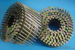


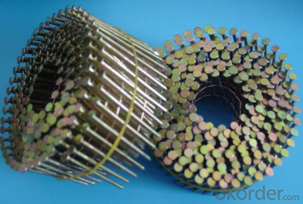
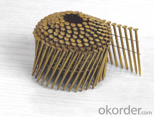
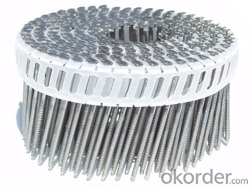
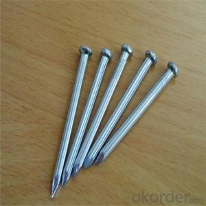
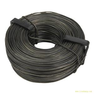
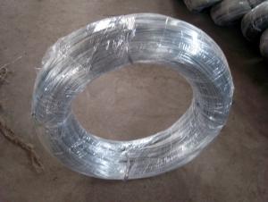
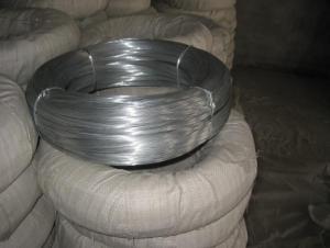
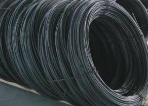
Electro Galvanized Coil Nails
- Ref Price:
-

- Loading Port:
- China Main Port
- Payment Terms:
- TT OR LC
- Min Order Qty:
- -
- Supply Capability:
- -
OKorder Service Pledge
OKorder Financial Service
You Might Also Like


Specifications
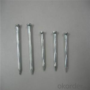
Length:10mm-200mm Shank Diameter(mm):1.80--6.50
arrcoding to requirement
Best price with high quality products must be provided,All progress will be informed you after you ordered,
BEST AND CHEAP WIRE COIL NAILS IN CHINA!
TOP CAPACITY MANUFACTURER!
CLAVOS HELICOIDALES ISO9001,CE,CNAS CETIFIED.WITH QUALITY CERTIFICATE.
5) nail length: from 15mm to 150mm
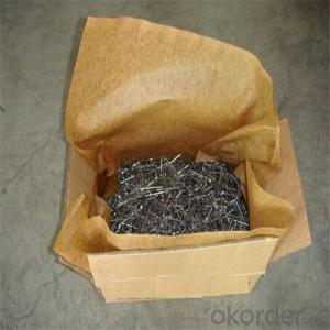
6) packing: 16000pcs/ctn; 9000pcs/ctn; 7500pcs/ctn; 5000pcs/ctn; 4500pcs/ctn; 4000pcs/ctn
7) degree: 15 or 16
Specification:
Body Dia. | Length | Head Dia. | PCS/Roll | |||
Inch | mm | Inch | mm | Inch | mm | |
0.083" | 2.1 | 1-1/4"~2" | 32~50 | 3/16" | 4.8 | 400PCS/COIL |
0.900" | 2.3 | 1-1/2"~2-1/4" | 38~57 |
| 5.3 | 350PCS/COIL |
0.099" | 2.5 | 1-3/4"~2-1/2" | 45~64 |
| 5.8 | 300PCS/COIL |
0.113" | 2.87 | 1-1/4"~3" | 57~75 | 1/4" | 6.3 | 250PCS/COIL |
0.120" | 3.05 | 2-3/8"~3-3/4" | 60~90 | 9/32" | 7.1 | 250PCS/COIL |
0.131" | 3.33 | 3"~4" | 75~130 | 9/32" | 7.1 | 120PCS/COIL |
| Diameter(length) | Shank diameter | Expansile diameter | Head diameter | Head thickness | First welding position | Second welding position | Inside Coil Diameter | |||
| | ||||||||||
| 2.1(25-38mm) | 2.1+/-0.02-0.05mm | 2.1+0.15-0.3mm | 5.0mm | 0.8mm | 8mm | 19mm | 25mm | |||
| | ||||||||||
| 2.1(45-50mm) | 2.1+/-0.02-0.05mm | 2.1+0.15-0.3mm | 5.0mm | 0.8mm | 19mm | 37mm | 32mm | |||
| | ||||||||||
| 2.3x38mm | 2.3+/-0.02-0.05mm | 2.3+0.15-0.3mm | 5.5mm | 0.8mm | 8mm | 19mm | 32mm | |||
| | ||||||||||
| 2.2-2.3(45-60mm) | 2.3+/-0.02-0.05mm | 2.3+0.15-0.3mm | 5.5mm | 0.8mm | 19mm | 37mm | 32mm | |||
| | ||||||||||
| 2.5(35-38mm) | 2.5+/-0.02-0.05mm | 2.5+0.15-0.3mm | 6.0mm | 1.0mm | 8mm | 19mm | 32mm | |||
| | ||||||||||
| 2.4-2.5(50-75mm) | 2.5+/-0.02-0.05mm | 2.5+0.15-0.3mm | 6.0mm | 1.0mm | 19mm | 37mm | 32mm | |||
| | ||||||||||
| 2.7-2.9(50-83mm) | 2.7+/-0.02-0.05mm | 2.7+0.15-0.3mm | 7.1mm | 1.0-1.1mm | 19mm | 37mm | 32mm | |||
| | ||||||||||
| 3.0-3.1(80-90mm) | 3.0+/-0.02-0.05mm | 3.0+0.15-0.3mm | 7.4mm | 1.3mm | 19mm | 37mm | 32mm | |||
| | ||||||||||
| 3.1x100mm | 3.1+/-0.02-0.05mm | 3.1+0.15-0.3mm | 7.4mm | 1.3mm | 19mm | 52mm | 32mm | |||
| | ||||||||||
Remarks:
Material: Q195/Q235
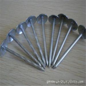
Surface Treatment: BRIGHT/E.G./HDG
Shank: SMOOTH/RING/SCREW
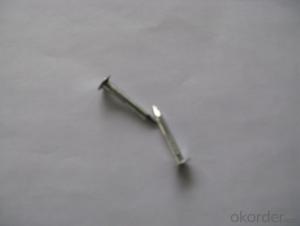
Nail point: diamond point; blunt point; chiesel point
Type: conical-coiled; flat-coiled
NAIL DIA.: 1.5MM--5.0MM
NAIL LENGTH: 15MM--150MM
Delivery time:10 days from S/C date
- Q: 14. Three parallel wires carry currents, with magnitudes and in the directions shown in the figure below. The wires all lie in a plane, and are all 2 m long, with separations between them as shown in the figure. What is the total force on wire #3 due to wire #1 and wire #2? Wire 1 : 6A, 2.5 m from Wire 3 ---------------------gt;Wire 2: 3A, 1.0 m from Wire 3 lt;--------------------Wire 3: 3A ---------------------gt;Can't figure it out, any hints/suggestions?
- The formula for force between wires is: (?/2π)(current1)(current2)(length/r) ? = 4πE-7 Tm/A r=distance between wires For this problem, you would just find the force on wire 3 of each one separately. Since wire 2 is going opposite direction as wire 3, they repel each other, while wire 1 and wire 3 attract each other since they are going same direction. I get Fwire1 to be 2.88E-6 N, and Fwire2 to be 3.6E-6N. Then subtract them since opposite forces, and since Fwire2 is stronger, the force would be 7.2E-7 N away/repelling.
- Q: I have a Speedaire 4B234 its currently wire to 120V but keep flipping the breaker and I have a 240V in the garage so I want to wire it to that. I have 2 blue wires, 2 red wire, and 2 green wires but the green wires are hooked together. One blue wire goes to Line and the other to Motor and same thing with the red wires.
- I looked up the specs on the 4B234. Says it CAN be wired to 240. You will just have to follow the wiring diagram on the motor or with the instructions. Specs say it pulls 15 amps at 120 v or 7.5 amps at 240 v. Your problem now is that maybe you only have a 15 amp or a 20 amp breaker. 15 amps is probably the continuous running draw. The current surge on start up goes over 20 amps and is what is flipping your breaker. you will need a double pole (2 wire) 20 amp breaker. wire it with #12 wire. Say a green, red, black. (or you can use blue and red) Green is always ground (should be). 240 volts works by being 2-120's out of phase by 180 degrees. One wire is pushing (+) while the other is pulling (-). You hook one wire to the motor in and the other to motor out. Running 240 will increase your efficiency.
- Q: why do we use copper wires as connecting wires
- For better conductivity and durability.
- Q: just need a little help to make right.just wiring an outlet from building to breaker box outside.. which way is the right way to wire it to a breaker then the box. Got the right breaker. Thanks
- in case you are able to desire to ask this question you don't comprehend adequate to do it suitable. Get an electrician to do it. you will the two electrocute your self or burn your place down in case you do it.
- Q: I am installing a GFCI outlet in the kitchen (20 AMP) the box that it is already installed in has more than nine wires running into it. What I need to know is how does one determine the load wires from line wires when there are multiple wires running to an outlet box?
- You use some test equipment to determine which is the line cable. All of the grounds are connected together. Identify each of the remaining wires with numbers BEFORE you disconnect anything. After that you can make a wiring drawing of the connection box and device before you disconnect anything. Once the drawing is done you can tun off the circuit(s) and begin the changes. The line/hot wire and it's neutral are connected to the G F I line connections, the load connections are made to protect any down line devices. If you do not need to protect the down line devices all of the connections can be made before the G F I device. If this seems too much of a challenge for you the best solution is to have a qualified professional electrician do the work.
- Q: I need to get to the audio wiring
- you cannot simply go with matching the colors factory radios have extra wires that are not needed with an aftermarket install most of the time (wires that control the dimmer on the radio, speed sensitive volume) you will need three power wires (constant, ignition, and ground), plus your speaker wires use a test light to test your wires, usually at the radio the yellow wire is your constant, the red is your ignition, and black is always ground to find your constant use the test light, it will be hot at all times so that your radio can remember the time, and your settings- next you need your ignition, it is only hot when the key is on or in the accessory position, to tell the radio when to come on- the ground is self explanatory to find which wires go to what speakers all you need is a 9v battery, put the positive end to a wire and test all of the other wires to the negative side and you will hear a crackling noise from a speaker when you have the right combination
- Q: thats how my after market stereo is hooked up..i just got a system and was wondering if i join the remote wire to the accessory would it be ok? even if the accessory is already joined with the illumination
- You need to first disconnect the accesory wire on the aftermarket radio from the illumination wire from the car harness if you are using hose connection to turn on the radio. You need to connect the accesory wire from the aftermarket radio to the accesory wire from the car radio harness, if you are using a wire harness then it would be the red wire and if the factory radio harness is cut then u'll need a test light to locate the accesory wire. On the aftermarket radio harness/plug locate the blue/white wire that's where u will need to connect the remote wire to, in order to turn your amp on and off. Don't connect the remote wire to the illumination wire from the car, or the radio harness.
- Q: How are wired differ from wireless doorbells,next how are they installed and finally the cost of them?
- Wired have a wire that connects the button near the door, the transformer, and the chime. When the button is pushed, the transformer energizes the chime, causing it to ring. You, or an electrician, must fish wires to a location where a transformer can get a constant supply of power, such as an outlet. There also need to be wires fished to the chime and the button. Wireless work with radio waves. Costs vary widely, depending on the setup you go with. Decent wireless units start around $35-40, and go up from there. New chimes for wired systems start around $8 and up. Transformers start at $10, buttons start around $5. Hope this helps.
- Q: Ok, bought this mower at an estate auction for next to nothing. It looks like its never been used. Previous owner ripped out all the wires to the ignition switch so it wouldn't sell I guess. It's the craftsman lt 1500. Model number 247.288812. It has the 17.5hp bs motor in it. Does anyone know the correct way the wires go to the switch? There are 3 red wires so its a bit unlike what im used to. Thanks in advance!
- On my sears mower with an electric clutch the switch is wired like this. G terminal is a black wire to ground. B terminal is a red wire to the ammeter. S terminal is a white wire to a safety switch. M terminal has two black wires one to the ignition coil and the other to a safety switch. L teminal is a red wire to the alternator and a red wire to the PTO switch.
- Q: ok...all the wires in my quot;atticare encased in this silver metal casing....when i opened a bathroom wall...the wires were also like that.....at the fuse box...they all leave like that........sooooo, can i assume all my wires are encased like that? does that make them pretty safe from rodents chewing? (yup-been watching Billy the Exterminator) why were they done like that? tx for any info....
- In the U.S. it WAS called BX and is now called MC, standing for metallic clad. (If the lines are flex-able). This stuff was used to protect from damage. This is usually used in commercial applications, but is perfectly legal (if the proper connectors were used) in residential applications. It sounds like you are doing a remodel. If so, you will need a EXPERIENCED electrician to modify the runs for you. Don't let anyone tell you it is against code. It is simply overkill.
Send your message to us
Electro Galvanized Coil Nails
- Ref Price:
-
- Loading Port:
- China Main Port
- Payment Terms:
- TT OR LC
- Min Order Qty:
- -
- Supply Capability:
- -
OKorder Service Pledge
OKorder Financial Service
Similar products

Hot products
Hot Searches
Related keywords

