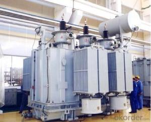

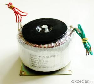
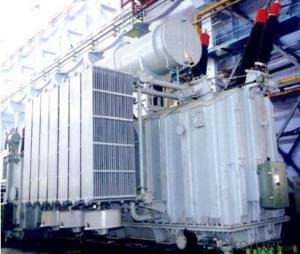
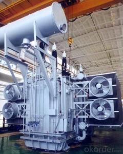
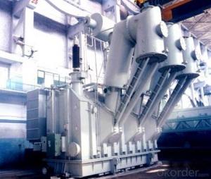
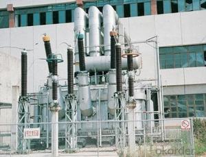
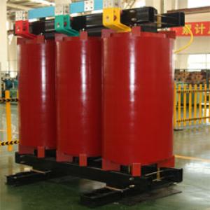
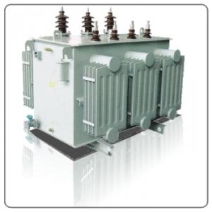
40MVA/20kV split auxiliary transformer for factory
- Ref Price:
-

- Loading Port:
- Tianjin
- Payment Terms:
- TT OR LC
- Min Order Qty:
- 1 pc
- Supply Capability:
- 1 pc/month
OKorder Service Pledge
OKorder Financial Service
You Might Also Like


Quick Details
| Place of Origin: | HeBei | Brand Name: | CNBM | Model Number: |
|
| Usage: | Power | Phase: | Coil Structure: | Toroidal | |
| Coil Number: | 3 Winding | Capacity: | Rated Voltage: | 40MVA/20kV | |
| Connection Symbol: | YNd11 Dyn11 YNyn0d11 | Tank: | Cover type or Bell type | OLTC: | MR or ABB or SMS |
Packaging & Delivery
| Packaging Detail: | Mainbody --naked Disassembled parts -- crate |
| Delivery Detail: | 3 months |
Specifications
1. CESI certificate
2. High short-circuit withstand
3. Low loss, PD and noise
4. CTQC certificate
5. No leakage
Description
The application of the 40MVA/20kV split auxiliary transformer, and matches well with the transmission capacity of UHV lines, which has wide prospect of application. Because of its large capacity and large volume, the whole transportation weight with nitrogen is about 200-490 tons, and due to the restricted transport conditions, the transportation becomes the critical issue for application of the 40MVA/20kV split auxiliary transformer. In order to make the products applicable to any UHV substation in our country, the state grid of corporation of China set the "A study of easy-transport large capacity UHV Transformer” as a key scientific research projects, and entrusted BTW to carry out the research.
During the process of research and development, BTW adopted the advanced design technology and modular design, the transformer can be transported disassembly and with advantages of compact core and winding body, less transportation weight and low transportation cost, effectively solves the need of UHV construction in the transportation restricted areas. By using the most advanced 3D magnetic field calculation software, BTW performed detailed analysis and calculation for the magnetic flux leakage and eddy current loss of the transformer coil, iron core and oil tank steel structures. Besides, by using of the advanced electric field calculation software, BTW performed detailed analysis and calculation of main longitudinal insulation, and mastered the arrangement of the main longitudinal insulation of large capacity UHV transformer and the control of distribution of winding magnetic flux leakage. All of which make the products with low loss, low noise, small volume, strong anti short circuit ability, no local overheating and other significant advantages, and guarantee the long-term safe and stable operation.
The world's first on-site assembled large capacity UHV Transformer’s right at the first time once again filled the gap in the field of UHV transformer research after Chinese transformer industry overcame the difficulty of integral transport of the 40MVA/20kV split auxiliary transformer, which marks BTW has fully occupied the world transformer industry technical peak. The successful development of the product filled the gaps in the domestic technology and met the urgent need of UHV construction application in our country, greatly improved the technical level and manufacturing ability of BTW in terms of UHV Transformer products.
- Q: 50KVA transformer maximum load is how much?
- Transformer (Transformer) is the use of electromagnetic induction principle to change the AC voltage of the device, the main components are primary coil, secondary coil and core (core). The main functions are: voltage conversion, current conversion, impedance conversion, isolation, voltage regulator (magnetic saturation transformer) and so on. According to the purpose can be divided into: power transformers and special transformers (electric furnace change, rectifier, frequency test transformer, voltage regulator, mine transformer, audio transformers, IF transformers, high-frequency transformers, impact transformers, instrument transformers, electronic transformers , Reactors, transformers, etc.). The circuit symbol is commonly used as the beginning of the number.
- Q: How do transformers work detailed descriptions please. Also how are the voltages stepped up or down?
- A transformer is a device that can be used to increase voltage and decrease current (or vice versa). It uses AC power and is based on Faraday's law of induction (mutual induction). A transformer is made up of two coils, each with a different number of turns, linked magnetically through a soft iron core. The magnetic flux from one coil links the other through the core. When the flux in one coil changes, the flux passing through the other will change, inducing a voltage (emf) in the second coil. The coil connected to the AC power source is known as the primary coil (number of turns Np), while the coil in which voltage is induced is known as the secondary coil (number of turns Ns). If the primary coil sets up a changing flux, the voltage in the secondary coil depends on the number of turns in the secondary. The transformer is assumed to be ideal in which the resistance of the coils is negligible and all the flux in the core links both primary and secondary windings. There will be no energy loss in an ideal transformer.
- Q: Audio output transformer
- If you don't want to buy one then rent it. There are a lot of electrical and electronics shops online that offer such service.
- Q: I really want a better transformers than 4 1 was great 2 was crap 3 good 4 worst of them all
- Unfortunately, there probably will be
- Q: I don't know much about Transformers but the movie looks great. So how many are there, and name them. Are they good or bad?
- Autobots (Good) Optimus Prime Ironhide Bumblebee Jazz Ratchet Decepticons (Bad) Megatron Blackout Starscream Barricade Scorponok Frenzy Bonecrusher Brawl
- Q: I am seeing the TRANSFORMERS series now for the 1st time, unfortunately I do not have all the EPISODES. Megatron turns to Galvatron, What Happens to OPTIMUS PRIME?? Does he change too?? Who is GALAXY CONVOY???What is the Final Episode of the Series, Who will be Alive at the End and Who is Defeated?? Please explain me in Detail,,,In Depth.Thanks in Advance.
- In the Transformers movie from the 80's, Optimus Prime is killed by Megatron. He gives the mantle of leadership to his 2nd in command (another large tractor trailer truck named Ultra Magnus) During his death though the mantle is handed to Hot Rod for a moment and the audience sees that he is the true leader it was meant for. At the end of the film he received the Mantle and becomes Rodimus Prime. Megatron however in fighting Optimus was gravely injured along with several other Decepticons. On the return flight to Cybertron, it is decided that they need to rid the ship of any unnecessary weight so as to make it possible to return (all the way) to Cybertron. Megatron is one of the last thrown over board and StarSCream becomes the new leader. As Megatron floats through space, he comes across the path of Unicron who is the largest transformer (Moon/planet size). He gives Megatron life again in the form of Galvetron. Only catch is he must serve Unicron. His first order of business of course is to kill Starscream (takes about 10 seconds). Convoy is Optimus Prime's name in Japan's version of the show. Additionally, in the series you are currently watching, Optimus is brought back to life twice and remains with them as leader through the end of the series. The series has had many lives so there is no definitive end to the characters yet. I could give you a ton of other info, but I think this is what you needed.
- Q: advantages of power transformers
- 1, less susceptible to parasitic thermocouples and pressure drop along the wire resistance and temperature drift of the transmission line can be very inexpensive twisted pair wire finer; 2, in the current source output resistance is large enough, the magnetic field sensor coupled to the wire the voltage loop will not have a significant impact, because the interference caused by the current is very small, usually using twisted pair can reduce the interference resistance; 3, the capacitive resistance of the receiver causes interference on the error, both for 4 ~ 20mA wire loop, the receiver resistance is usually 250 (sample Uout 1 ~ 5V) that resistance small enough to produce significant errors, therefore, can allow the cable length longer than the voltage telemetry system further; 4, each single display device or recording device can be read in the wire lengths between the different channels for access, not caused by wire length ranging between accuracy; 5, 4mA to zero level, to determine the open circuit or sensor is damaged (0mA state) is very convenient. 6, in the easy addition of two-line outlet surge and lightning protection devices, is conducive to safe mine explosion.
- Q: I can't remember the funny scenes from any the Transformers movies, especially 1 and 2.It's driving me nuts.I saw the third one just last week so I remember a couple of funny scenes, but other than that, no luck.If you can, could you please include a link to a video clip of the scene?Thanks so much! (:
- When the car turns into bumblebee and the guy says to the girl its probably japanese
- Q: Hi there.I have purchased a Stepdown Transformer so i can use a Record Cleaning Machine I am buying from the U.S.It uses a powered suction unit to clean the record.All transformers for use with American equipment have 110v output, but i think your equipment is usually 120v.in I have been told that there is nothing to worry about as 110v out on the transformer is enough to power the equipment connected to it .Our AC output in Australia is 240v but we can use any voltage from 220 to 250. Therefore 110v should be enough.can anyone clarify and tell me it should be ok.Thanks a lot in advance.
- I was in Germany for 2 years they are 220v also. I had a 110v step down and it worked fine with a TV VCR and a electric razor.
- Q: A 2300/230 V step down transformer is rated at 70 kVA and 60 Hz. Its windings have the following resistances and inductances : Rp 0.093 ohms, Xp0.280 ohms, Rs 0.00093 ohms and Xs 0.00280 ohms. The transformer's rated current at the secondary is 3261 A. Assume that a10 from 2300/230 V and calculate the no load voltage for unity 0.7 lagging and 0.7 leading power factor.
- this is quite a typical question. there will be many examples similar to it
Send your message to us
40MVA/20kV split auxiliary transformer for factory
- Ref Price:
-
- Loading Port:
- Tianjin
- Payment Terms:
- TT OR LC
- Min Order Qty:
- 1 pc
- Supply Capability:
- 1 pc/month
OKorder Service Pledge
OKorder Financial Service
Similar products
Hot products


Hot Searches
Related keywords

