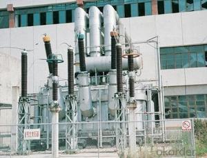
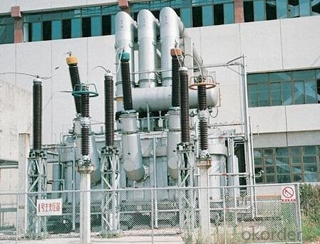
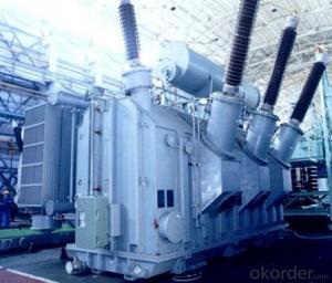
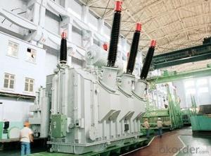
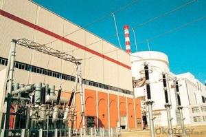
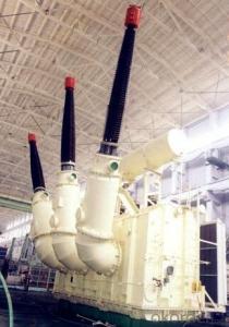
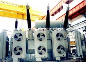
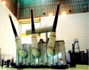
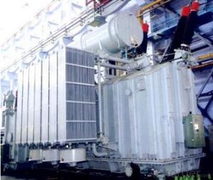
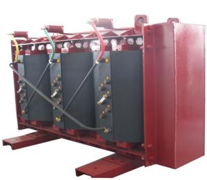
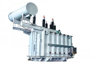
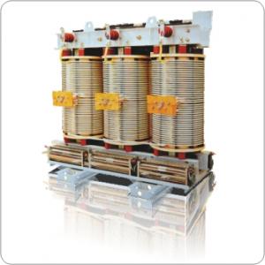
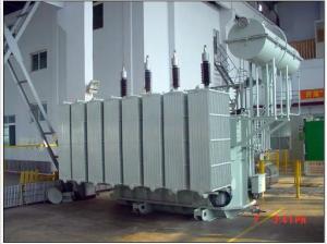
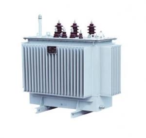
400MVA/220kV main transformer power plant
- Loading Port:
- Tianjin
- Payment Terms:
- TT OR LC
- Min Order Qty:
- 1 pc
- Supply Capability:
- 1 pc/month
OKorder Service Pledge
OKorder Financial Service
You Might Also Like
Quick Details
| Place of Origin: | HeBei | Brand Name: | CNBM | Model Number: |
|
| Usage: | Power | Phase: | one | Coil Structure: | Toroidal |
| Coil Number: | 2 Winding | Capacity: | Rated Voltage: | 400MVA/220kV | |
| Connection Symbol: | YNd11 Dyn11 YNyn0d11 | Tank: | Cover type or Bell type | OLTC: | MR or ABB or SMS |
Packaging & Delivery
| Packaging Detail: | Mainbody --naked Disassembled parts -- crate |
| Delivery Detail: | 3 months |
Specifications
1. CESI certificate
2. High short-circuit withstand
3. Low loss, PD and noise
4. CTQC certificate
5. No leakage
Description
The application of 400MVA/220kVmain transformer power plant can significantly improve the economy of the OLTC substation, and matches well with the transmission capacity of OLTC lines, which has wide prospect of application. Because of its large capacity and large volume, the whole transportation weight with nitrogen is about 470-490 tons, and due to the restricted transport conditions, the transportation becomes the critical issue for 400MVA/220kV main transformer power plant. In order to make the products applicable to any OLTC substation in our country, the state grid of corporation of China set the "A study of easy-transport large capacity OLTC Transformer” as a key scientific research projects, and entrusted BTW to carry out the research.
During the process of research and development, BTW adopted the advanced design technology and modular design, the transformer can be transported disassembly and with advantages of compact core and winding body, less transportation weight and low transportation cost, effectively solves the need of OLTC construction in the transportation restricted areas. By using the most advanced 3D magnetic field calculation software, BTW performed detailed analysis and calculation for the magnetic flux leakage and eddy current loss of the transformer coil, iron core and oil tank steel structures. Besides, by using of the advanced electric field calculation software, BTW performed detailed analysis and calculation of main longitudinal insulation, and mastered the arrangement of the main longitudinal insulation of large capacity OLTCtransformer and the control of distribution of winding magnetic flux leakage. All of which make the products with low loss, low noise, small volume, strong anti short circuit ability, no local overheating and other significant advantages, and guarantee the long-term safe and stable operation.
The world's first on-site assembled large capacity OLTC Transformer’s right at the first time once again filled the gap in the field of OLTC transformer research after Chinese transformer industry overcame the difficulty of integral transport of 400MVA/220kV main transformer power plant, which marks BTW has fully occupied the world transformer industry technical peak. The successful development of the product filled the gaps in the domestic technology and met the urgent need of OLTCconstruction application in our country, greatly improved the technical level and manufacturing ability of BTW in terms of OLTC Transformer products.
- Q: What is the difference between transformer MVA and KVA?
- MVA = 1000KVA Is the usual representation of the transformer capacity.
- Q: I want my car to be a transformer
- My Penis Transforms!
- Q: I need x-mas gifts for transformer toys! Please help thank you!
- I need x-mas gifts for transformer toys! U R giving gifts to Transformers toys?, Just go to any Wal*Mart, Target, KB Toys store they have lots of Transformers toys. They have a lot of selection @ Toys R Us(2007 movie, Beast Wars, classic, Energon and more)
- Q: I read something somewhere once about using small mains transformers as substitute speaker transformers in valve circuits.Suppose I have a 6-0-6V transformer with a 240V primary. That gives a 20:1 turns ratio. So if the secondary is putting out Vs volts at Is amps into 8 ohms, then (neglecting losses) the primary will have 20*Vs volts across it and Is/20 amps through it. But we know that Is Vs / 8; so the primary will appear to have an impedance of (20 * Vs) / (Vs / 160) 3200 3.2k ohms.Am I thinking right? Or will the presence of DC in the primary ruin everything?I'm thinking of using an ECL82 (aka 6BM8) for my first project, as that has both a triode and a pentode with separate cathodes and seems to be available still. Is this a good choice?
- Mains Transformers
- Q: I loved transformers as a kid, but recently, I've rediscovered them. Now I want all of them again, especially Masterpiece editions. Yeah, they're cool, but wtf?!? Why do I want them so bad? I'm looking at a FOC Grimlock that I'm about to customize and resell. He doesn't know. Why do I want these toys as an adult man?!? Yes, I have a hot wife and kids and a decent career, so shut up with the dumb(er) stuff. Thanks!
- As long as it doesn't interfere with the important things in life, I don't see anything wrong with recapturing some of your youth with the toys you once loved. I mean, you (and I) *are* the target audience for the Masterpiece Transformers--at $100-$200 a pop, with fairly complicated transformations, and specifically designed to look like the G1 cartoon versions of the characters, these Transformers aren't for today's kids, they're for us '80s kids who now have disposable income and will spend the money for the definitive version of the G1 characters we grew up with. That's why we want them--they're made for us to want. :D Every guy has a hobby (and probably more than just one). Collecting fancy Transformers really isn't that different from, say, souping up cars, or putting together a home theater, or collecting Blu-rays, or whatever else guys our age are into. And besides, if you get over your Transformers bug, you can always sell or pass on your collection to someone else. Over the years I've picked up the Masterpiece versions of Optimus Prime, Megatron, Starscream, and Grimlock, and more recently I've sold off all of them except Optimus (yeah, I'm going to hang on to him); even though they were all loose, I actually wound up selling them for more than I paid for them new (that's how prized some of these Masterpieces are).
- Q: A step-up transformer is connected to a generator that is delivering 131 V and 96 A. The ratio of the turns on the secondary to the turns on the primary is 859 to 1. What voltage is across the secondary? An-swer in units of kV.What current flows in the secondary? Answer in units of mA.
- a step up transformer is connected to the generator. therefore the voltage on the primary side of the transformer is 131 volts. secondary turns/primary turns secondary voltage/primary voltage. therefore voltage on secondary side 131*859 112.529KV secondary turns/primary turns primary current/secondary current therefore current on the secondary side 96/859 111.756mA. in order to cross verify, the power on primary side power on the secondary side. i.e 131*96112.529KV*111.756mA.
- Q: I think the power supply to my external hard drive has failed. Is there anyway I could replace the transformer. There is no way to contact the manufacturers as they have the worst customer services ever (Formac). I have emailed them 5 days ago without a reply.
- Im assuming you are just talking about a plug in adapter with the transformer built in. If you look on the face of the transformer pack it should give you a VA rating and a voltage rating. You can buy a new one as long as you match the numbers. Hope this helps.
- Q: I was just curious if they ever had an episode or something where somebody manipulated a captured transformer and was able to control it or something, or something that turned someone into a transformer. far fetched ya but god knows the stuff that's out there these days, so I was just wondering.
- no they don't
- Q: Every yellow vehicle we pass on the road is BUMBLEBEE!!! and big trucks are opinus PWIME! And, he is constantly singing Twansfomahs, more dan meets dah eye! LOL So, I wanted to find him something for Easter that was transformers related, but as it's Easter, and NOT Christmas, I don't want to spend a lot of money. Suggestions?
- at his age most any robot toy would suffice. enjoy, this stage goes by very fast
- Q: i have a bunch of transformers and they have the dates like i have optimus prime it says takara hasbro 1980-1982 and all the other toys say hasbro or takara! and most are made from 1982 -1985 also i have jet fire but the stamp doesn't say hasbro or takara but it does say bandai 1984!
- i'll answer throughly. bandai is a japanese brand which produce toys. but you asked how do i tell if my transformers are G1 or real. you can tell by its looks. g1 models looks like a box (quite square in shape), but the latest 1 looks modern.
Send your message to us
400MVA/220kV main transformer power plant
- Loading Port:
- Tianjin
- Payment Terms:
- TT OR LC
- Min Order Qty:
- 1 pc
- Supply Capability:
- 1 pc/month
OKorder Service Pledge
OKorder Financial Service
Similar products
Hot products
Hot Searches
Related keywords
