
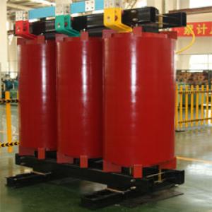
40MVA/110KV generator startup/standby transformer
- Ref Price:
-

- Loading Port:
- Tianjin
- Payment Terms:
- TT OR LC
- Min Order Qty:
- 1 pc
- Supply Capability:
- 1 pc/month
OKorder Service Pledge
OKorder Financial Service
You Might Also Like


Quick Details
| Place of Origin: | HeBei | Brand Name: | CNBM | Model Number: |
|
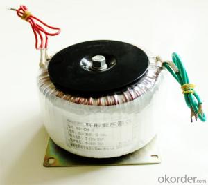
| Usage: | Power | Phase: | Coil Structure: | Toroidal | |
| Coil Number: | 3 Winding | Capacity: | Rated Voltage: | 40MVA/110KV | |
| Connection Symbol: | YNd11 Dyn11 YNyn0d11 | Tank: | Cover type or Bell type | OLTC: | MR or ABB or SMS |
Packaging & Delivery
| Packaging Detail: | Mainbody --naked Disassembled parts -- crate |
| Delivery Detail: | 3 months |
Specifications
1. CESI certificate
2. High short-circuit withstand
3. Low loss, PD and noise
4. CTQC certificate
5. No leakage
Description
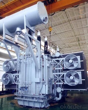
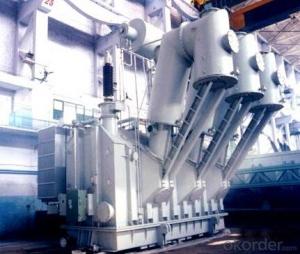
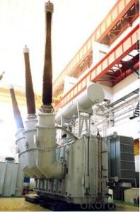
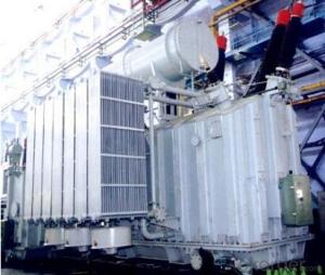
The application of the 40MVA/110KV generator startup/standby transformer, and matches well with the transmission capacity of OLTC lines, which has wide prospect of application. Because of its large capacity and large volume, the whole transportation weight with nitrogen is about 200-490 tons, and due to the restricted transport conditions, the transportation becomes the critical issue for application of the 40MVA/110KV generator startup/standby transformer. In order to make the products applicable to any OLTC substation in our country, the state grid of corporation of China set the "A study of easy-transport large capacity OLTC Transformer” as a key scientific research projects, and entrusted BTW to carry out the research.
During the process of research and development, BTW adopted the advanced design technology and modular design, the transformer can be transported disassembly and with advantages of compact core and winding body, less transportation weight and low transportation cost, effectively solves the need of OLTC construction in the transportation restricted areas. By using the most advanced 3D magnetic field calculation software, BTW performed detailed analysis and calculation for the magnetic flux leakage and eddy current loss of the transformer coil, iron core and oil tank steel structures. Besides, by using of the advanced electric field calculation software, BTW performed detailed analysis and calculation of main longitudinal insulation, and mastered the arrangement of the main longitudinal insulation of large capacity OLTC transformer and the control of distribution of winding magnetic flux leakage. All of which make the products with low loss, low noise, small volume, strong anti short circuit ability, no local overheating and other significant advantages, and guarantee the long-term safe and stable operation.
The world's first on-site assembled large capacity OLTCTransformer’s right at the first time once again filled the gap in the field of OLTC transformer research after Chinese transformer industry overcame the difficulty of integral transport of the 40MVA/110KV generator startup/standby transformer, which marks BTW has fully occupied the world transformer industry technical peak. The successful development of the product filled the gaps in the domestic technology and met the urgent need of UHV construction application in our country, greatly improved the technical level and manufacturing ability of BTW in terms of OLTC Transformer products.
- Q: A 120 kVA, 7000/277 V (What does this rating mean) distribution transformer has the following resistances and reactances: Rp 5.5 ohms Xp 6.5 ohms Rs 0.007 ohms Xs 0.008 ohms Rc 55 kohms Xm 15 kohms The excitation branch impedance are given referred to the low voltage side of the transformer: a) What's the equivalent circuit of the transformer referred to the low voltage side b) What's the the per unit equivalent circuit c) Assume that this is supplying rated load at 277V and 0.89 lagging power factor, What is the transformer input
- 120 kVA, 7000/277 V (What does this rating mean) Primary voltage rating: 7000 V, secondary voltage rating: 277 V, rated load: 120 kVA It is unclear whether this is a single-phase or three-phase transformer. You probably need to assume it is single-phase. The equivalent circuit of a 3-phase transformer is analyzed as one of three single-phase transformers that could be connected to make the equivalent Y-Y three-phase transformer. The secondary voltage, 277 V, is the line to neutral voltage for a 480 V, wye distribution system. That is a USA standard system voltage. The primary would be 12,124 V L-L, 7000 V L-N. That would a reasonable primary distribution system voltage. Referring the circuit to the low side means changing the primary component values to the equivalent secondary values and moving the ideal transformer to the primary side of the circuit as shown below. To change the primary impedance values, multiply by (Sec V/Pri V)^2.
- Q: High school physics, according to the transformer U1 / U2 = N1 / N2 Can make a large voltage into a small voltage, but the small voltage can become a large voltage? Need no conditions? Can the transformer be used only for alternating current? I am now only high school physical level, answer not too esoteric or too professional! Thank you !!
- Small voltage can become large voltage. If only in the theoretical considerations, as long as meet the N1 <N2, you can make U1 <U2.
- Q: hello. I've been thinking about this long and hard. you see ever since I was 2 years old I've been collecting transformers figures and other items. now that I'm getting older I know I must let go. but its kind of hard when for the first 8 years of m life my transformers were all I had. and I know when we die we will leave these things behind. but it seems so hard to let go. so what would you do if you were in my sitiuationcause this is very hard for me and i'm lost. I know in heaven we will all be happy but it seems weird to me will I not remeber transformers?if anyone has any ideas that would be great thanks.
- I've collected Transformers for the first few generations I quit about buying the toys after Transformers: The Movie (cartoon) was released. I have Cyclonus and the Combiners but aside from that, I haven't bought many after that. Transformers went downhill with the introduction of Galvatron and the new generation of Transformers. I'd keep the Transformers for now It'll be hard to get many of them, especially with the bio cards and all the weapons the toy came with originally. Hold onto them and they should rise in value. I keep mine in the addict, they've been there for years and will remain there for many more until I want to revisit them to see if I remember what weapons go to which toy, heh.
- Q: I really want a better transformers than 4 1 was great 2 was crap 3 good 4 worst of them all
- Yes, there will be a Transformers 5. When we don't know. Many people are thinking 2016 or 2017, but i have a friend that works in the movie theater and she knows the next movies for the next 2 years and Transformers 5 was not on the list. Is that because Transformers 5 has no name yet? Maybe. So Im assuming its coming out in 2017 or 2018. As for Paramount pictures they are not even thinking about Transformers 5 yet. As they stated once its one movie at a time.
- Q: I am going to see Transformers tonight at an 8:00 pm showing. Do you think there will be a big line to see it? Should I show up earlier to get a good seat or do you think going a 1/2 hour before the show starts, like I usually do, will be enought time to get good seats?
- If I were you, I would wait until the movie was out on DVD. This way, you can see it whenever you like. Who knows? You just might enjoy it.
- Q: What are the malfunctions and abnormal operation of the transformer? What is the difference between them and the line?
- Transformer failure: can be divided into the tank failure and tank failure. Fuel tank failure: a short circuit between the windings, short-circuit between the turns, direct grounding system side winding short circuit. Outside the tank failure: There is a short circuit between the casing and the lead wire and the ground short circuit (direct grounding system side). Transformer is not working properly: there are external faults caused by over-current, overload, oil level and due to over-voltage or frequency caused by over-excitation and so on. Line fault: phase short circuit (including three-phase short circuit, two-phase short circuit), two-phase ground short circuit, single-phase ground short circuit, transmission line disconnection.
- Q: Do you think if I asked this. which I am maybe people will pick Transformers because more Americans watch Trans instead of Gundam but if people watched both, would they still pick Transformers?
- What, in a battle or as in an anime? If it's anime, I pick Gundam. If it's a battle. Well Transformers got someone called Unicorn who's the size of a Planet. So you can imagine how powerful he is.
- Q: A neon sign transformer has a 350 W AC output with an rms voltage of 13 kV when connected to a normal household outlet. There are 500 turns of wire in the primary coil.A How many turns of wire does the secondary coil have?B When the transformer is running at full power, what is the current in the secondary coil?C The current in the primary coil?I know what equations I would use, but I don't have enough information to use them. Can someone at least set these up and show me how to plug the numbers I have into the correct equations?
- A neon sign transformer has a 350 W AC output with an rms voltage of 13 kV when connected to a normal household outlet. There are 500 turns of wire in the primary coil. Power output Power input Power Volts * Amps 350 13,000 * amps Amps 0.0269 amps current in the primary coil? House voltage 120 volts 350 120 * amps Amps ≈ 2.92 current in the secondary coil? Amp Ratio 2.92 ÷ 0.0292 100 : 1 Wire ratio 100 : 1 A How many turns of wire does the secondary coil have? 50,000
- Q: I read something somewhere once about using small mains transformers as substitute speaker transformers in valve circuits.Suppose I have a 6-0-6V transformer with a 240V primary. That gives a 20:1 turns ratio. So if the secondary is putting out Vs volts at Is amps into 8 ohms, then (neglecting losses) the primary will have 20*Vs volts across it and Is/20 amps through it. But we know that Is Vs / 8; so the primary will appear to have an impedance of (20 * Vs) / (Vs / 160) 3200 3.2k ohms.Am I thinking right? Or will the presence of DC in the primary ruin everything?I'm thinking of using an ECL82 (aka 6BM8) for my first project, as that has both a triode and a pentode with separate cathodes and seems to be available still. Is this a good choice?
- you have 2 issues there. a million. Voltage; 2. Frequency. to that end, the two are against you. NZ has 50Hz mains frequency at 240V. in case you're relatively fortunate, the transformer could have twin windings on the universal, or a 220/240V. faucet. in case you do no longer understand what you're doing, seek for suggestion from an electrician or electronics tech. to have them examine regardless of if it relatively is twin voltage, and alter it. The frequency distinction can recommend incredibly much less performance, the transformer could get a sprint warmer in operation. even in spite of the shown fact that it may be high quality. you basically different thoughts are to alter the transformer (get one for twin voltages?), or use a 240/110V stepdown transformer earlier than it. The stepdown transformer could have a sufficient potential score for the interest.
- Q: Exactly what is the storyline of the Transformers. As far back as I know, there were two brother, Unicron and Primus who fought each other because Unicron wanted to suck up Universes. But where did these two come from? Does it even say?
- I am a fan but I haven't been able to find that out myself, if you find out let me know.
Send your message to us
40MVA/110KV generator startup/standby transformer
- Ref Price:
-
- Loading Port:
- Tianjin
- Payment Terms:
- TT OR LC
- Min Order Qty:
- 1 pc
- Supply Capability:
- 1 pc/month
OKorder Service Pledge
OKorder Financial Service
Similar products

Hot products


Hot Searches
Related keywords

