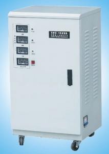
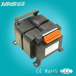
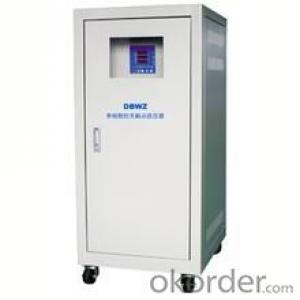
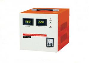
SVC NEW Single-phase And Three-phase High Accuracy Full Automatic AC Voltage Stabilizer
- Ref Price:
-

- Loading Port:
- Shanghai
- Payment Terms:
- TT OR LC
- Min Order Qty:
- -
- Supply Capability:
- 10000pcs pc/month
OKorder Service Pledge
OKorder Financial Service
You Might Also Like


1. Summary
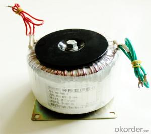
SVC-D Series AC automatic voltage regulator is the latest product studied and produced by ourselves. These products adopt 8 digits CPU control produced by the well-known MOTOROLA company, which can stabilize the precision and set up the delay time. The products also have many protection functions on delay, over-voltage invert-delay, lack voltage, over load invert-delay, lack voltage, over load, over temperature, machine malfunction and so on. They have digital display, blue-screen lightproof, dynamic panel display and it can show the working status of the machine. When the machine works abnormally, on the panel there is corresponding due and short or long warning.
| Specification | 0.5KVA,1KVA,1.5KVA,2KVA,3KVA,5KVA |
| Input Voltage | (1)AC 150V~250V (2)AC 70V~130V |
| Output Voltage | AC (1)220V (2)110V |
| Stabilization Precision | When 220V,±3% When 110V,±3% |
| Frequency | 50Hz,60Hz |
| Delay Time | Long:180s;Short:5s |
| Over-voltage Protection Value | (1)250V/5s delay; (2)275V/2s delay; (3)295V/1s delay; (4)305V/0s |
| Lack-voltage Protection Value | 180V/5s delay |
| Over-load Protection Value | 2.8times than rated capacity |
| Over-temperature Protection Value | 90oC |
| Load Capacity Factor | cos 0.9 |
| Regulating Time | When input varies 10%,less than 1s |
| Waveform Distrotion | No additional waveform distortion |
| Reactance Strength | 1500V/1min |
| Insulation Resistance | >5MΩ |
| Insulation Grade | E grade |
| Environment | Temperature:-10oC~+40oC Humidity:<90% |
- Q: A small transformer used in a foundry has 550 primary turns and 20 secondary turns. Initially, the switch on the secondary side of the transformer is open, so there is no connection between the two ends of secondary coil.(a) What is the voltage difference between the two ends of the secondary coil, Vs, if a direct current potential of Vp 120 V is placed across the primary coil? (That is, the frequency of oscillation on the primary is zero.) (b) What is the voltage difference between the two ends of the secondary coil, Vs if Vp is 120 V and the frequency of oscillation on the primary is 60Hz? (c) Now equipment powered by the transformer is put into use and the switch is closed. A resistance of 14 Ω is placed between the two ends of the secondary coils. What is the current through the secondary coil? (d) What is the current through the primary side of the coil with the switch closed? Thanks so much!!
- A. Zero, since dc current does not have a varying magnetis field. B. 550/120 20/ X 4.3636volts Ne /E p Ns / E s C.4.3636v / 14 .311 a. Es / R t A s D. .011 amp if the transformer is 100% efficient
- Q: i took it out. on one side of the transformer i have a black and a red im hooking those up to a battery on the other side i have five wires 2 red, 2 white, and 1 blue i dont know what these do or how to get current to them. does anyone know how to complete the circuit???
- You are trying to duplicate the Kettering ignition. Momentarily touching a battery to the lowest ohmage winging will usually get you a spark from one or more of the other windings. The old (my era) radios had a secondary to produce high voltage 400-600 volts (often centertapped) and a filament winding 5-6 volts. You would touch the battery to the filament winding and get the spark from the 4-6 hundred volt winding. If you used 110 volts ac on the black and red wires you would get a continuous 4-6 hundred volts AC from the secondary winding with enough amperage to kill someone.
- Q: I got stuck in a problem while solving the previous exam question for my courseTwo transformers with unequal turn ratio and unequal ratings are connected in parallel and have the same secondary voltage. How will the load be distributed between them? Hence find the circulating current.I know how to find the circulating current when the secondary voltages are different. But how can there be a circulating current if the secondary voltage is same?And I know about the load distribution being inversely proportional to the line impedance of the transformers, but what will be the change taking circulating current into account?
- To me it is a typical circuit analysis problem. From an application engineers point of view , to analyse the problem, the following needs to be checked first 1) Open circuit Voltage of both the TRXs 2) Internal impedences of TRXs 3) Total Load to be catered to ( converted to in terms of Z) 4) Ratings of the TRXs ( Rather allowable current that can be drawn from each TRXs) Having known first three quantities , we can make the parallel circuts and calculate the current in each branch ( through TRX1, TRX2, and the load) andtheir directions The fourth quantity will tell us if loading is within limit or not.
- Q: 100kVA above the transformer grounding resistance is how much
- 100kVA above the transformer grounding resistance should not exceed 10 Europe. Transformer (Transformer) is the use of electromagnetic induction principle to change the AC voltage of the device, the main components are primary coil, secondary coil and core (core). The main functions are: voltage conversion, current conversion, impedance conversion, isolation, voltage regulator (magnetic saturation transformer) and so on. According to the purpose can be divided into: power transformers and special transformers (electric furnace change, rectifier, frequency test transformer, voltage regulator, mine transformer, audio transformers, IF transformers, high-frequency transformers, impact transformers, instrument transformers, electronic transformers , Reactors, transformers, etc.). Circuit symbols commonly used as the beginning of the number. Example: T01, T201 and so on.
- Q: I realize this may be super simple but i cant for the life of me figure out how to open a wall mount transformer it seems like they are snapped shut with no way to open?
- They are glued, or even sonically welded. They are made to be replaced not repaired. They can be open by sawing a knotch in the corner and prying open with a screwdriver.
- Q: i heard that there is an electric transformer used in single phase electric furnace and other applications , its benefit is to get more balanced current load from the three phase system to feed a single phase load.i need to know how its can transform three phase supply into single phase supply, and if it can be used in reverse matter i.e can it deliver a three phase power from single phase supplythank you in advance
- this okorder
- Q: What are the transformer capacity?
- Transformer capacity: 15,30 50 63 80 100 125 160 200 250 315 500 630 A high - speed range of 12500 .. The The The The (Unit: KVA) Small is less than 1600KVA Medium 1600--6300KVA Large 8000 - 63000KVA Extra large is greater than 63000KVA
- Q: 220 volts to 24 volts transformer 20a is how many watts
- Transformer consists of iron core (or core) and coil, the coil has two or more than the winding, which connected to the power supply winding called the primary coil, the rest of the winding called secondary coil. It can transform AC voltage, current and impedance. The simplest core transformer consists of a core made of soft magnetic material and a coil of two turns on the core, as shown in the figure. Turn left to turn right The role of the core is to strengthen the magnetic coupling between the two coils. In order to reduce the iron in the eddy current and hysteresis loss, the core from the painted silicon steel sheet laminated; between the two coils there is no electrical connection, the coil by the insulated copper wire (or aluminum) A coil connected to the AC power supply is called the primary coil (or the original coil), and the other coil is called the secondary coil (or secondary coil). The actual transformer is very complicated, inevitably there is copper loss (coil resistance heating), iron loss (core fever) and magnetic flux leakage (by air closed magnetic induction line), etc., in order to simplify the discussion here only describes the ideal transformer. The ideal transformer is set up under the condition that the leakage flux is ignored and the resistance of the original and secondary coils is ignored. The loss of the core is ignored and the no-load current is ignored (the current in the secondary coil turns the original coil). For example, when the power transformer is running at full load (the secondary coil output rated power) is close to the ideal transformer situation.
- Q: hello thank you for reading this question, i have a iron cored dc-ac transformer (relies on interrupter to constantly break circuit to induce induction in secondary coil) a brief and crude diagram can be found
- If I understand correctly, you want to turn an old transformer into an electromagnet, and you want to use both windings in order to get the strongest possible field. First of all, you are going to need to modify the core: It needs a gap. In a perfect transformer, the lines of magnetic force would be entirely confined to the core.
Send your message to us
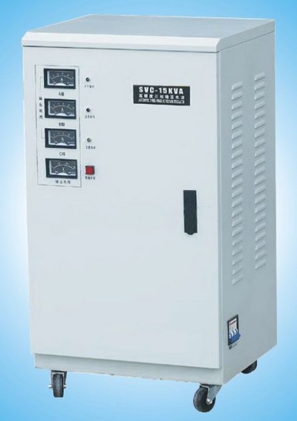
SVC NEW Single-phase And Three-phase High Accuracy Full Automatic AC Voltage Stabilizer
- Ref Price:
-
- Loading Port:
- Shanghai
- Payment Terms:
- TT OR LC
- Min Order Qty:
- -
- Supply Capability:
- 10000pcs pc/month
OKorder Service Pledge
OKorder Financial Service
Similar products

Hot products


Hot Searches
Related keywords

