


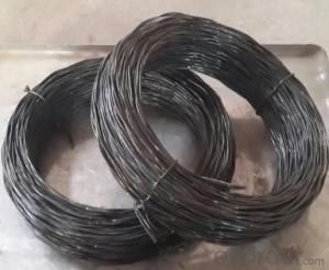
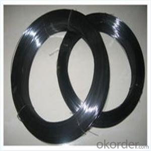
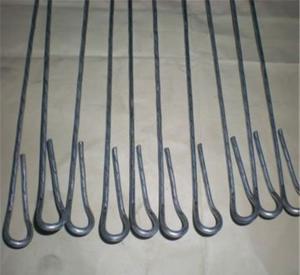
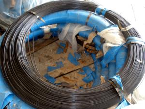
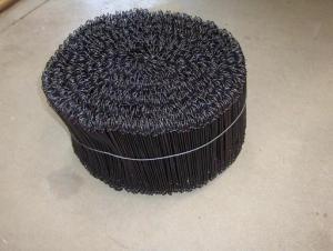
PVC Coated Iron Wire For Binding the the rebar
- Ref Price:
-

- Loading Port:
- Tianjin
- Payment Terms:
- TT OR LC
- Min Order Qty:
- 5 m.t.
- Supply Capability:
- 1000 m.t./month
OKorder Service Pledge
OKorder Financial Service
You Might Also Like


Introduction
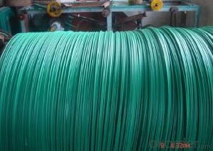
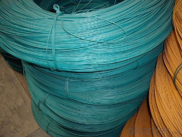
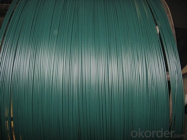
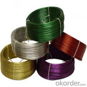
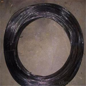
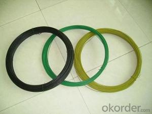
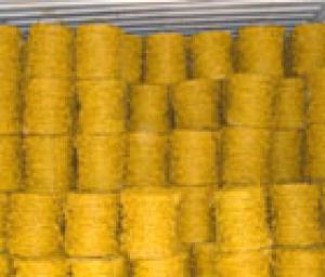
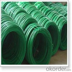
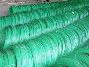
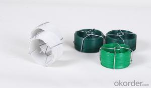
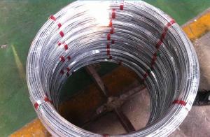
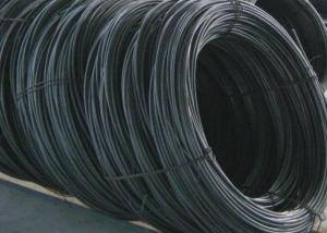
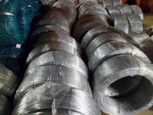
The PVC coated wire is made by inner metal and coating. The inner metal can use black iron wire and galvanized wire. Various colors can be provide for you, such as yellow, red, green, white, etc. It is low in cost, corrosion resistance, strong adhesion, good luster, aging resistance and weather resistance.
Colors
Usually are green and black. Other colors like blue, yellow, orange, gray, red also are available. Or as customer’s requests.
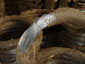
Feature
It is relatively low in cost, beautiful and firmly, wear-resistant, corrosion-resistant, crack-resistant, and fire retardant possesses good insulating properties.
Technology
PVC coated wire is widely used in animal breeding, forestry protection, aquaculture, park or zoo fence and stadium.
Application
PVC coated wire is widely used in animal breeding, forestry protection, aquaculture, park or zoo fence and stadium.


- Q: I have two DVC subs and I know how to wire them down to 1 ohm with the wires coming out of one outlet on the box but I don't know how to wire them down to 1 ohm with wires coming out of both sides of the box. Anyone have a wiring diagram for this?
- For okorder /... On the inside of the enclosure, connect both positives and both negatives to the enclosure inside terminal. That makes each side of the enclosure 2 ohms. Mount and screw in the subs. Now, on the outside: 1) Observing polarity, run short jumpers between the terminals (positive to positive, negative to negative) and then connect ONE set of terminals to the amp (again observing polarity) (positive to positive, negative to negative. 2) Run separate wires from each set of terminals to the amp, observing polarity. That makes the final impedance to the amp 1 ohm.
- Q: Well I have a mono D and it has - - + + on it and I want to to wire my dvc 4ohm sub to 2 ohms but I'm not sure what terminals I hook the speaker wire up to?
- wire okorder /... and than wire it to any of the negatives on the amp its all one channel internally so it really doesn't matter which negative u use. than wire the positive to any positive on the amp.
- Q: 1) How does the type of wire affect resistance?2) How does the length of wire affect resistance?3) How does the diameter of the wire affect resistance?4) How does temperature affect resistance?
- 1) How does the type of wire affect resistance? - This property is called resistivity changes from material to material very low for metals 2) How does the length of wire affect resistance? - If material and other dimensions are same it increases in the same ratio as the length.[If l doubles resistance doubles] 3) How does the diameter of the wire affect resistance?- If material and other dimensions are same itdecreases in the same ratio as the square of the diameter.[If diameter doubles resistance becomes one fourth] 4) For metals, the resistivity increases linearly with temperature. 4) How does temperature affect resistance?
- Q: Would crepe paper stick on chicken wire?
- Crepe paper needs an adhesive to make it stick to a surface, such as white glue. However, it gets messy once dampened, as the colors may bleed. Instead, I would consider working with paper mache or plaster gauzing strips, which would provide a strong skin over the chicken wire. Both can be primed with gesso then decorated with acrylic paints. If this is a sculptural piece you want to keep, we would also suggest varnishing it for protection.
- Q: You have a 3 foot wide wire, vs a .3 inch wire. They are equal length. There is 3 volts going through each wire, to power your 1 volt LED. So, would the 3 foot wide wire have less resistance ? I don't even think it would work.
- 'sure` bigger wires have decrease resistance. 'No' on the transformer component of your question. With the transformers, 'magnetic saturation` performs a substantial section in cutting-edge limiting. The impedance of a transformer isn't in effortless terms resistance. Google or Wiki 'Choke coil'
- Q: how do i wire a dual 2 ohm sub to an amp at 2 ohm
- You can't. Dual 2 ohm subs can only be wired at 1 ohm or 4 ohm. To run an amp at a 2 ohm load you need a dual 4 ohm sub. You can get a second dual 2 ohm sub to match and then they can be wired together at a 2 ohm load.
- Q: I have a 2002 chevy trailblazer lt and i was trying to see if anyone knows what color is what for the radio harness i want to straight wire my aftermarket cd player in because the harness is 100 dollars to buy. if anyone can tell me which wire goes to where by color or know of a good diagram i would appreciate it.
- Go to Auto Zone and buy a Haynes manual on the truck, it will have the wiring diagrams in the back
- Q: I have a 1997 Dodge Neon 2DR and i did a electric door and mirror conversion but i cannt figure out the wiring... how would i go about figuring it out... can some explain or better show me how a basic lock and mirror controls are wired
- i own a repair shop,and if you,ll get a good Haynes repair manual on it,this will have the wiring diagrams in it,for doing this ,that's about the only way you can wire it up right on this job,good luck,i hope this help,s.
- Q: What are the advantages and disadvantages of a bank wire transfer ?
- its just a transfer of funds from one account to another --- usually overseas --- most intracountry transfers can be accomplished online today ---- it depends on how much you need to transfer and to whom --- there are much easier and cheaper ways to transfer funds --- credit cards, international transfers such as western union, international postal orders ---- have fun
- Q: Electron flow in a conducting wire.?I have some confusion regarding the flow of electrons in a wire when voltage is applied across it. Intuitively, i see that when i apply voltage across the ends of the wire say by a battery. The voltage pushes the electrons in the wire. As, a result the electrons flow in straight direction rather than going zig-zag. Some of the electrons reach the positive terminal of the battery, now my query is what happens when the electrons reach the positive terminal.Do they loose all their energy? Also, how is there a constant flow of electrons in the wire because since electrons are flowing constantly from the negative to the positive, is there no instance all the free electrons in the wire have reached the positive terminal? Basically what i mean to say is do the free electrons ever gets extinct? I am sorry if my question sounds stupid but can anyone please explain me a little bit in a conceptual manner?
- The pace of the electron is variable relying upon the the style of energy you are dealing with. In our case, electrons waft within the conductor, though it's sluggish, it is only like ping-pong balls(Analogous to electrons) inside of a say, plastic pipe slanted down ward. When you provide a bit little bit of strain( i.E. Electrical Voltage or emf in our case) one pushes the other and the other one to the subsequent one so on momentarily (Which is very rapid action). This is how you to find the light turned on immediately once you turn the swap On. I feel is the brief answer for the query. Thank you.
Send your message to us
PVC Coated Iron Wire For Binding the the rebar
- Ref Price:
-
- Loading Port:
- Tianjin
- Payment Terms:
- TT OR LC
- Min Order Qty:
- 5 m.t.
- Supply Capability:
- 1000 m.t./month
OKorder Service Pledge
OKorder Financial Service
Similar products
Hot products
Hot Searches
Related keywords

