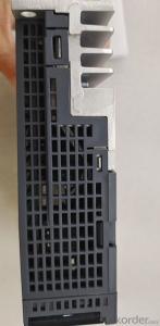


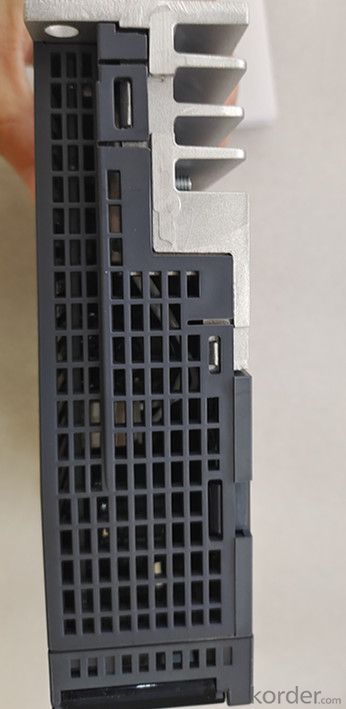
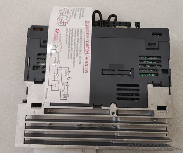

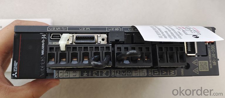
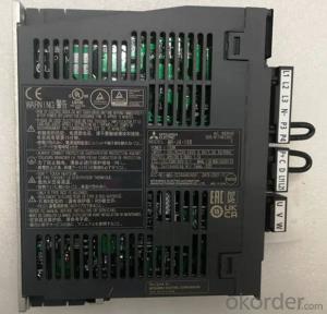
Three-Phase Or Single-Phase Universal Type MR-J4-20B Servo Amplifier
- Ref Price:
-

- Loading Port:
- Shanghai
- Payment Terms:
- TT OR LC
- Min Order Qty:
- 1 kg
- Supply Capability:
- 2000 kg/month
OKorder Service Pledge
OKorder Financial Service
You Might Also Like


Specification
Specification of sscnetiii / h mr-j4-20b for Mitsubishi servo amplifier 200W:
[output]
. rated voltage: three-phase ac170v
. rated current: 1.5A
[main circuit power input]
. power frequency: three-phase or single-phase ac200v ~ 240V 50Hz / 60Hz
. rated current: 1.5A
. allowable voltage variation: three-phase or single-phase ac170v ~ 264v
. allowable frequency variation: ± 5%
. capacity of power supply equipment: 0.5kva
. surge current: 30A (reduced to about 3A after 20ms)
[control circuit power input]
. power frequency: single phase ac200v ~ 240V 50Hz / 60Hz
. rated current: 0.2A
. allowable voltage variation: three-phase or single-phase ac170v ~ 264v
. allowable frequency variation: ± 5%
. power consumption: 30
. surge current: 20 ~ 30A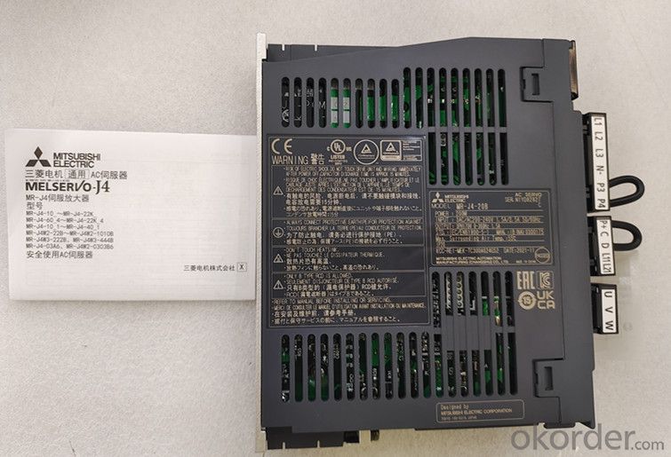
[power supply for interface]
. voltage? Frequency: DC24V ± 10%
. power capacity: 0.3A (including CN8 connector signal)
[control mode] sine wave PWM control current control mode
[dynamic brake] built in
[communication function]
. USB: connection with personal computer, etc. (corresponding to Mr
configurator2)
[position control mode]
. maximum input pulse frequency: 4mpps (differential input), 200kpps (open
collector input)
. positioning feedback pulse: encoder resolution (resolution of servo motor per
revolution) 22 bits
. command pulse magnification: electronic gear A / b times a = 1 ~ 16777216, B
= 1 ~ 16777216, 1 / 10 < A / b < 4000
. positioning completion pulse width setting: 0pulse ~ ± 65535pulse (command
pulse unit)
. excessive error: ± 3 Revolutions
. torque limit: set through parameter setting or external analog input (dc0v ~
+ 10V / maximum torque)
[speed control mode]
. speed control range: analog speed command 1:2000, internal speed command
1:5000
. analog speed command input: dc0v ~ ± 10V / rated speed (the speed at 10V can
be changed through [pr.pc12])
. speed change rate: ± 0.01% (load change: 0% ~ 100%), 0% (power change: ±
10%) ± 0.2% (ambient temperature: 25 ± 10 ℃). Only when analog speed command
is available
. torque limit: set through parameter setting or external analog input (dc0v ~
+ 10V / maximum torque)
[torque control mode]
. analog torque command input: dc0v ~ ± 8V / maximum torque (input impedance:
10K? ~ 12K?)
. speed limit: set through parameter setting or external analog input (dc0v ~
± 10V / rated speed)
[protection function]
Overcurrent protection, regenerative overvoltage protection, overload
protection (electronic thermal relay), servo motor overheating protection
Encoder abnormal protection, regeneration abnormal protection, insufficient
voltage protection, instantaneous power failure protection
Overspeed protection and excessive error protection
[safety function] sto (IEC / en 61800-5-2)
[safety performance]
. third party certification specification: EN ISO 13849-1 type 3 PL D, en 61508
SIL 2,
EN 62061 SIL CL2,EN 61800-5-2 SIL 2
. response performance: less than 8ms (STO input off → energy cut-off)
. test pulse input (STO): test pulse cycle: 1Hz ~ 25Hz test pulse off time:
max. 1ms
[structure (protection level)] self cooling open (IP20)
[compact installation] adjustable
[weight] 0.8kg
- Q: if i take a small transformer meant to be used at 120v:9v 60hz, and discharge a 360v 100uf capacitor (or similar) into the 9v winding, will i get a high voltage pulse on the 120v winding?
- You just described a frequently-used principle. Don't tase me, bro!
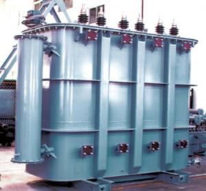
- Q: Transformer 1250KVA Dimensions
- 10kV grade distribution transformer oil immersion 1250KVA appearance size 1786X1170X1410 (length X width X height); dry 1250KVA appearance size 1470X1200X1450 (length X width X height), for reference, the specific best asked suppliers.
- Q: About a month ago, i studied Ohm's law which said voltage is directly proportional to electric current. But today when i was studying about transformer, it said that if number of turns of the secondary coil is more than that of primary, then the induced voltage is higher than the primary voltage which was supplied and the current throught the secondary coil is less. How can this be? If voltage increases, current should also increase right? And what is the difference between emf and current?
- Ohm's regulation, the place it applies, will consistently artwork. the significant factor is the place it applies. on your case, the present is decreased via a million/20 interior the secondary whilst in comparison with the present interior the regularly occurring. however the fee of the secondary present day might nicely be calculated via making use of ohms regulation in case you have a resistor load. case in point, in case you have a one hundred volts utilized to the regularly occurring, then the secondary is 2000 volts. in case you have a a million M? load, the secondary present day is 2000/1M 2 mA. meaning the regularly occurring present day is 20 x 2mA 4 hundred mA. in case you alter the burden to 100k?, then the secondary present day is 20 mA and the regularly occurring present day is 4 amps.
- Q: i need a little help with my homework. if you bank three single phase dual voltage transformers in a delta connection for the primary and do the same for the secondary, do the kva of primary add together or do the kva stay the same because it is connected in delta.it's a 2:1 480v - 240v each transformer is 5 kvais the total kva when connected in delta 15 kva or 5 kva and do you use the formula Pa line current times line voltage times 1.73 to find the rated load current.thanks in advance
- With 3-5KVA transformers connected inbank, your total capacity is 15Kva.To find the line current: Kva 1.732[V](I)/1000. Line current, I KVA{1000]/1.732{V) I 15[1000]/480*1.732 I 18.042, volts at primary.
- Q: I am building a high voltage RF transformer and I'm wondering what considerations I need to take in order to build it correctly.The transformer primary will be powered by a 12V square wave signal around 5-20kHz. The secondary needs to put out at least 1kV at very low amperage (in the mA range, the lower the better).What considerations I need to take into account in building the transformer?Thanks for all the help!
- I should think your primary concern should be the safety angle. How will the transformer be isolated from the public?
- Q: How much W?
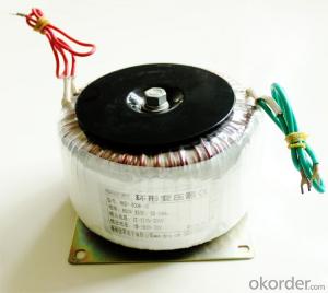
- Ee22 transformer can be 20W. Transformer (Transformer) is the use of electromagnetic induction principle to change the AC voltage of the device, the main components are primary coil, secondary coil and core (core). The main functions are: voltage conversion, current conversion, impedance conversion, isolation, voltage regulator (magnetic saturation transformer) and so on. According to the purpose can be divided into: power transformers and special transformers (electric furnace change, rectifier, frequency test transformer, voltage regulator, mine transformer, audio transformers, IF transformers, high-frequency transformers, impact transformers, instrument transformers, electronic transformers , Reactors, transformers, etc.). Circuit symbols commonly used as the beginning of the number. Example: T01, T201 and so on.
- Q: I need a transformer to use american electronics in Ireland, any websites that sell Type G transformers?
- You need a step-down transformer to reduce the 230 VAC to 115 VAC for your American devices. The web site below is one good source. It has transformers to step voltages up or down. A transformer is the best way to go as opposed to a voltage converter that just uses a voltage drop. Make sure the transformer you get has enough power capacity to supply everything you want to connect to it.
- Q: I heard that a transformer is like a ratio device for amps and volts, but I know there must be more to it. How exactly does it work, and what happens when it doesn't have enough current, but enough voltage?
- reliable question. to respond to your question, no it wouldnt paintings like that. Transformers substitute AC voltage not DC present day. the way it truly works is that the AC enter creates a magnetic container in the different edge, coming up present day and voltage. in spite of the shown fact that it truly is proportional to the windings on each and each coil. in case you wind one coil on the enter to each 5 on the output, you have created a a million:5 transformer. you put in x voltage and get out 5x. before everything this appears like unfastened means. yet you're actually not elevating present day and voltage. certainly means would desire to stay the comparable. means volts * amps. hence, in case you enhance the voltage, you shrink the present. The strobe mild circuits interior cameras substitute a a million.5V AA battery into approximately 1000V. the present in spite of the shown fact that, is plenty smaller.
- Q: In the transformer load calculation to be calculated when the fire pump
- The fire pump is not included in the normal operation of the transformer load, because when the fire pump is running, but also when the fire, the other load had to stop. The usual fire pump test check, the pump start running time is very short, the transformer allows a short time overload.
- Q: I have a small question concerning flyback transformers. I have run into some confusing problems when i tried testing the flyback using the High voltage power supply project
- You might find whether your transformer is broken with an ohmmeter between the ultor cap and a pin by trying each with the meter set to a high ohms range, with (I think) the black meter lead connected to the ultor. If you don't see a result 1st. time around, try swapping the meter leads. If you get a result, try the 24V test there. If you don't, and using his method also fails, I think you have a dud. So far as the 9V test, I think that has a fatal flaw. A digital multimeter, or usually also an analogue one, cannot respond fast enough to a single pulse. A digital meter only samples at a certain rate, and if the voltage does not align with the sampling, you see nothing. Even if it does, I think you would only see an instantaneous reading before next sample sees nothing. Apart from that, the voltage spike will be well over 200V! The object is to sort out input direction in the primary. I would suggest you sort out the primary connections, and build the circuit. I have not looked at it, but I think if you fire it up, you will either have + HV coming from the ultor cap, or nothing. If nothing, reverse the primary. DON'T TEST IT WITH YOUR FINGERS!!!
Send your message to us
Three-Phase Or Single-Phase Universal Type MR-J4-20B Servo Amplifier
- Ref Price:
-
- Loading Port:
- Shanghai
- Payment Terms:
- TT OR LC
- Min Order Qty:
- 1 kg
- Supply Capability:
- 2000 kg/month
OKorder Service Pledge
OKorder Financial Service
Similar products
Hot products


Hot Searches

